Download
1 / 15
170 likes | 595 Views
Radio Propagation. Spring 07 CS 527 – Lecture 3. Overview. Motivation Block diagram of a radio Signal Propagation Large scale path loss Small scale fading Interesting link measurement observations Implications of protocol design. Motivation for Wireless propagation.

E N D
Radio Propagation Spring 07 CS 527 – Lecture 3
Overview • Motivation • Block diagram of a radio • Signal Propagation • Large scale path loss • Small scale fading • Interesting link measurement observations • Implications of protocol design
Motivation for Wireless propagation • Wireless channel is vastly different from wired counterpart • Different access mechanisms • Common channel but … • State of channel at each node can vary drastically • E.g.: Sender thinks that channel is free but receiver senses a busy channel – Packet drop? • Unreliable channel • Highly sensitive to environment (surroundings) and weather • Modest bandwidth • Effects of Propagation has a high impact on higher layer protocols • E.g.: Are the assumptions made by TCP protocol valid under wireless channel?
Modulation Antenna Coding Demodulation Decoding Antenna Radio Block Diagram • In today's class: • How does the signal propagate? What are the prominent effects?
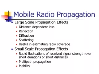
Signal Propagation Effects • Large scale Path loss • Large distances (w.r.t. to wavelength of the wave) between transmitter and receiver • Small scale Fading • Fluctuation in received signal strengths due to variations over short distances (w.r.t. to wavelength of the wave) • Consider the wavelength of radio signals for 802.11 • 802.11 a: Frequency = 5.2 GHz Wavelength = 5.8 cm • 802.11 b/g: Frequency = 2.4 GHz Wavelength = 12.5 cm
Large scale Path loss • General Observation: • As distance increases, the signal strength at receiver decreases • Free-space Propagation model: • Line-of-Sight (LoS) based • E.g.: Satellite Communication, Microwave LoS Radio Links • Signal strength observed at receiver is inversely proportional to square of distance
Is it so simple? • But in realistic settings, lot of factors act on the wave • Three major reasons: • Reflection: From objects very large (wrt to wavelength of the wave). • Diffraction: From objects that have sharp irregularities. • Scattering • From objects that are small (when compared to the wavelength) • E.g.: Rough surfaces Figures borrowed from [1]
Accounting for Ground Reflection • Two-ray (Ground reflection) model • Considers LoS path + Ground reflected wave path ELOS Transmitter ETOT = ELOS + Eg Ei Receiver Eg θi θo Figures partially borrowed from [Rappaport]
Empirical models • Above models are very simplistic in realistic settings • E.g: Points 4 and 5 in the above figure • Alternative Approach: • Use empirical data to construct propagation models • But, can measurements at few places generalize to all scenarios? • Different environments? • Different frequencies? • Recognize "patterns" in the empirical data and use statistical techniques for approximating. Figures borrowed from [1]
Empirical Models • Log-distance Path loss model • Uses the idea that both theoretical and empirical evidence suggests that average received signal strength decreases logarithmically with distance • Measure received signal strength near to transmitter and approximate to different distances based on above “reference” observation • Log-normal shadowing • Observes that the environment can be vastly different at two points with the same distance of separation. • Empirical data suggests that the power observed at a location is random and distributed log-normally about the “mean” power
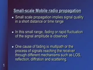
Small scale fading • Rapid fluctuations of the signal over short period of time • Invalidates Large-scale path loss • Occurs due to multi-path waves • Two or more waves (e.g: reflected/diffracted/scattered waves) • Such waves differ in amplitude and phase • Can combine constructively or destructively resulting in rapid signal strength fluctuation over small distances Example of Multipath Phase difference between original and reflected wave Figures borrowed from [http://www.iec.org/online/tutorials/smart_ant/topic05.html]
Factors affecting fading • Multipath propagation • Speed of mobile/surrounding objects • The frequency of the signal varies if relative motion between transmitter and receiver • E.g: The difference of sound heard when train is moving towards you or away from you • Transmission bandwidth • Discussion related to Lecture-2: • Does mobility increase/decrease the throughput while thinking about mobile computing? • Large scale/ Small scale? Figures borrowed from [http://www.glenbrook.k12.il.us/GBSSCI/PHYS/CLASS/waves/u10l3d3.gif]
Link measurement observations • Distance v/s observed signal strength • Is propagation disk shaped? • Directionality due to environment? • Does it observe Free-space Propagation model? Figure 2: Contour of probability of packet reception wrt distance Figure 1: SNR values v/s distance Figure 1 borrowed from [Aguayo – Link level measurements in 802.11b mesh network] Figure 2 borrowed from [Deepak Ganesan -- Complex]
Link measurement observations • Temporal variations • Shows packet reception rates of 4 different links • Temporal variations over a long time period (96 hours) is significant • Note: This is not the signal strength, but packet reception rate (broadcast packet) Figure borrowed from [Cerpa – Temporal]
Impact of protocol design • MAC protocol • Constant retransmissions needed • Neighborhood discovery • More problems when we consider asymmetry of links • Source can talk to receiver but not vice-versa • ACKs? • Routing protocol • Multi-hop reliability is low after 4 to 5 hops • Consider 5 links each with packet-throughput 95%. Overall throughput (assuming no ACK) is 95%. Overall throughput (assuming no ACK) is ~77%. • Transport protocol • Effect of unpredictable packet losses on TCP? • And other effects like packet delivery success based on relative motion between transmitter and receiver • Multipath effects?