Download
1 / 11

E N D
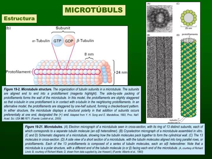
MICROTÚBULS Estructura Figure 19-2. Microtubule structure. The organization of tubulin subunits in a microtubule. The subunits are aligned end to end into a protofilament (magenta highlight). The side-by-side packing of protofilaments forms the wall of the microtubule. In this model, the protofilaments are slightly staggered so that α-tubulin in one protofilament is in contact with α-tubulin in the neighboring protofilaments. In an alternative model, the protofilaments are staggered by one-half subunit, forming a checkerboard pattern. In either structure, the microtubule displays a structural polarity in that addition of subunits occurs preferentially at one end, designated the (+) end. Adapted from Y. H. Song and E. Mandelkow, 1993, Proc. Nat'l. Acad. Sci. USA 90:1671. (Fuente: Lodish et al., 2000) Figure 16-21. Microtubules. (A) Electron micrograph of a microtubule seen in cross-section, with its ring of 13 distinct subunits, each of which corresponds to a separate tubulin molecule (an α/β heterodimer). (B) Cryoelectron micrograph of a microtubule assembled in vitro. (C and D) Schematic diagrams of a microtubule, showing how the tubulin molecules pack together to form the cylindrical wall. (C) The 13 molecules in cross-section. (D) A side view of a short section of a microtubule, with the tubulin molecules aligned into long parallel rows, or protofilaments. Each of the 13 protofilaments is composed of a series of tubulin molecules, each an α/β heterodimer. Note that a microtubule is a polar structure, with a different end of the tubulin molecule (α or β) facing each end of the microtubule. (A, courtesy of Richard Linck; B, courtesy of Richard Wade; D, drawn from data supplied by Joe Howard.) (Fuente: Alberts et al., 1993)
Acoblament Nucleació Allargament Estat Estacionari Figure 16-23. Polymerization of pure tubulin. A mixture of tubulin, buffer, and GTP is warmed to 37°C at time zero. The amount of microtubule polymer, measured by light-scattering, follows a sigmoidal curve. During the lag phase individual tubulin molecules associate to form metastable aggregates, some of which go on to nucleate microtubules. The lag phase reflects a kinetic barrier to this nucleation process. During the rapid elongation phase, subunits add to the free ends of existing micro-tubules. During the plateau phase, polymerization and depolymerization are balanced because the amount of free tubulin has dropped to the point where a critical concentration has been reached. For simplicity, subunits are shown coming on and off the microtubule at only one end. (Fuente: Alberts et al., 1993) Polimerització de tubulina in vitro
La hidròlisi del GTP desprès de la polimerització desestabilitza els microtúbuls Figure 16-33. GTP hydrolysis after polymerization destabilizes microtubules. Analysis of the growth and shrinkage of microtubules in vitro suggests the following model for dynamic instability. (A) Addition of tubulin heterodimers carrying GTP to the end of a protofilament causes it to grow in a linear conformation that can readily pack into the cylindrical wall of the microtubule, thereby becoming stabilized. Hydrolysis of GTP after assembly changes the conformation of the subunits and tends to force the protofilament into a curved shape that is less able to pack into the microtubule wall. (B) In an intact microtubule, protofilaments made from GDP-containing subunits are forced into a linear conformation by the many lateral bonds within the microtubule wall, especially in the stable cap of GTP-containing subunits. Loss of the GTP cap, however, allows the GDP-containing protofilaments to relax to their more curved conformation. This leads to progressive disruption of the microtubule and the eventual disassembly of protofilaments into free tubulin dimers. (Fuente: Alberts et al., 1993)
Inestabilitat dinàmica dels microtúbuls in vitro Figure 19-13. Dynamic instability of microtubules in vitro. Individual microtubules can be observed in the light microscope, and their lengths can be plotted during stages of assembly and disassembly. Assembly and disassembly each proceed at uniform rates, but there is a large difference between the rate of assembly and that of disassembly, as seen in the different slopes of the lines. During periods of growth, the microtubule elongates at a rate of 1 μm/min. Notice the abrupt transitions to the shrinkage stage (catastrophe) and to the elongation stage (rescue). The microtubule shortens much more rapidly (7 μm/min) than it elongates. [Adapted from P. M. Bayley, K. K. Sharma, and S. R. Martin, 1994, in Microtubules, Wiley-Liss, p. 119.] (Fuente: Lodish et al., 2000)
1.3. Centres Organitzadors de Microtúbuls Figure 19-5. Microtubule-organizing center. (a) Fluorescence micrograph of a Chinese hamster ovary cell stained with antibodies specific for tubulin and a centrosomal protein. The microtubules (green) are seen to radiate from a central point, the microtubule-organizing center (MTOC), near the nucleus. The MTOC (yellow) is detected with an antibody to Cep135, a protein in the pericentriolar material. (b) Electron micrograph of the MTOC in an animal cell. The pair of centrioles (red), C and C′, in the center are oriented at right angles; thus one is seen in cross section, and one longitudinally. Surrounding the centrioles is a cloud of material, the pericentriolar (PC) matrix, which contains γ-tubulin and pericentrin. Embedded within the MTOC, but not contacting the centrioles, are the (−) ends of microtubules (MT; yellow). [Part (a) courtesy of R. Kuriyama; part (b) from B. R. Brinkley, 1987, in Encyclopedia of Neuroscience, vol. II, Birkhauser Press, p. 665; courtesy of B. R. Brinkley.] (Fuente: Lodish et al., 2000)
Proteïnes Associades a Microtúbuls Figure 16-35. A microtubule-associated protein. (A) Electron micrograph showing the regularly spaced side arms formed on a microtubule by a large microtubule-associated protein (known as MAP-2) isolated from vertebrate brain. Portions of the protein project away from the microtubule, as shown schematically in (B). (Electron micrograph courtesy of William Voter and Harold Erickson.) (Fuente: Alberts et al., 1993)
1.5. Proteïnes Motores: Quinesina i Dineïna al Moviment Citoplasmàtic Dineïna Quinesina Figure 16-37. Microtubule motor proteins. Kinesins and cytoplasmic dyneins are microtubule motor proteins that generally move in opposite directions along a microtubule (A). These proteins (drawn here to scale) are complexes composed of two identical heavy chains plus several smaller light chains. Each heavy chain forms a globular head region that attaches the protein to microtubules in an ATP-dependent fashion. (B and C) Freeze-etch electron micrographs of a kinesin molecule (B) and a molecule of cyto-plasmic dynein (C). (Freeze-etch electron micrographs prepared by John Heuser.) (Fuente: Alberts et al., 1993)
Transport vesicular mediat per quinesina i dineïna Neurona Fibroblast Figure 16-38. Vesicle transport in two directions. Kinesin and cytoplasmic dynein carry their cargo in opposite directions along microtubules, as illustrated in a fibroblast (A) and in the axon of a neuron (B). (Fuente: Alberts et al., 1993)
Cilis, flagels i centríols Estructura de l’axonema de cilis i flagels Figure 19-28. Structure of ciliary and flagellar axonemes. (a) Cross-sectional diagram of a typical flagellum showing its major structures. The dynein arms and radial spokes with attached heads occur only at intervals along the longitudinal axis. The central microtubules, C1 and C2, are distinguished by fibers bound only to C1. (b) Micrograph of a transverse section through an isolated demembranated cilium. The two central singlet microtubules are surrounded by nine outer doublets, each composed of an A and a B subfiber (Fuente: Lodish et al., 2000)
(A) Estructura dels cossos basals als flagels de l’alga Chlamydomonas reinhardtii Figure 19-29. Electron micrograph of the basal regions of the two flagella in Chlamydomonas reinhardtii. The bundles of microtubules and some fibers connecting them are visible in the flagella (FL). The two basal bodies (BB) form the point of a “V”; a transition zone (TZ) between the basal body and flagellum proper contains two dense-staining cylinders of unknown structure. [From B. Huang et al., 1982, Cell 29:745.] (Fuente: Lodish et al., 2000). B) Color photo of Chlamydomonas, where the red color results from the auto-fluorescence of chlorophyll and the green from the binding of a fluorescent antibody to a plasma membrane glycoprotein (Fuente: Alberts et al., 1993).
Estructura del centríol o corpuscle basal Figure 16-45. Basal bodies. (A) Electron micrograph of a cross-section through three basal bodies in the cortex of a protozoan. (B) Diagram of a basal body viewed from the side. Each basal body forms the lower portion of a ciliary axoneme, and it is composed of nine sets of triplet microtubules, each triplet containing one complete microtubule (the A tubule) fused to two incomplete microtubules (the B and C tubules). Other proteins [shown in red in (B)] form links that hold the cylindrical array of microtubules together. The structure of a centriole is essentially the same. (A, courtesy of D.T. Woodrow and R.W. Linck.) (Fuente: Alberts et al., 1993)