Download
1 / 11
110 likes | 285 Views
Gluing. David Bailey. Silicon /pcb assembly. Previously Using Sony Robot and precision dispenser Have established acceptable glue dot parameters Dot electrical resistances < 0.005 Ohm ( Gold /dot/Gold) Need good control on gap thickness.

E N D
Gluing David Bailey
Silicon /pcb assembly Previously Using Sony Robot and precision dispenser Have established acceptable glue dot parameters Dot electrical resistances < 0.005 Ohm ( Gold /dot/Gold) Need good control on gap thickness Now modifying commercial BGA workstation as demonstration pick and place tool to position wafers on glued pcb. Wafers not handled manually Manual operation of workstation but shows automated concept
Glue Dot dispensing Sony dispensing robot Placing glue dots 18 x 18 (324) dots on 5mm grid (1 wafer ) 0.2 sec/ dot takes ~ 5min Highly reproducible
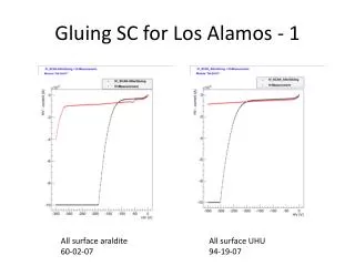
Dot size dependence on gap spacing 200m Glass plate wedge spacing Ø1.6 mm Ø2.0 mm Ø2.5 mm +/- 50 micron gap = +/- 0.5 mm diameter Ø3.6 mm 0
Dot resistance tests 12 x 6 dots @0.2 sec on CALICE test board Each pad probe able from rear Two boards sandwiched together, 66µm gap Interpad links cut on top board 4 Terminal resistances between overlapping pads measured – <0.005Ω per pad Needs repeating with silicon wafer
Wafer Pick and place demonstrator Modifying existing commercial BGA placement station to pick and place wafers on to glued pcb held on vacuum jig. Alignment via split prism viewing system. Align images of wafer pixels and PCB pixels. Manual operation could be automated with pattern recognition • rebuild pick up vac chuck • for 90 mm wafer • base vac chuck to hold PCB • Investigate spacing control ideas • - vacuum transfer chuck Assistance from Scott Kolya
Schematic of wafer assembly steps • 4 wafers (red) picked and aligned on BGA station relative to pcb pattern ( orange) . Held in position by vacuum. 2. Transfer chuck lowered on top.Vacuum top on, bottom off. Wafers now held on transfer chuck 3. Remove transfer chuck from BGA workstation maintaining vacuum • 5. Transfer chuck with wafers • placed on bottom jig. • Alignment dowels/touch bearings Fine tune height. Maintain vac during cure • Pcb (blue) held flat in • bottom vac jig . Glue robot dispenses dots 6. Remove assembled board
Vacuum Transfer Jig controls Portable vacuum Jig Control Trolley with resevoir for moving transfer jigs from glue robot to alignment workstation Panel controls vacuum on/off to the various jigs.
Summary • System has been “checked out” • Testing with boards from Cambridge • Have glass plates in hand • Have a couple of real wafers • Will attach to boards and check resistances • Pretty much ready to go • Waiting for the real ASU boards • Probably need to check how flat they are on the back with the ASIC in place