Download
1 / 46
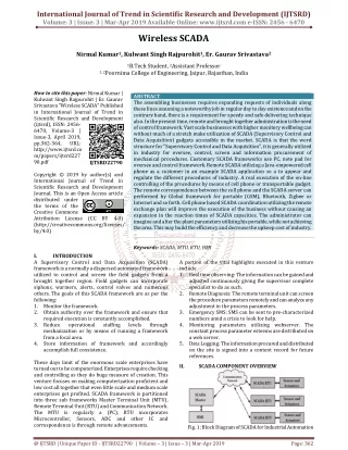
490 likes | 510 Views
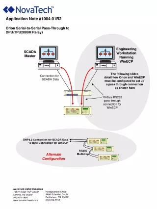
SCADA-Functions. Author, Vineeta Agarwal Place PSTI, Bangalore Date 29-4-2011. Responsibilities of RLDCs. Operation, monitoring and control of Regional Grids. Control of Central Sector Transmission System. Allocation of Central Sector Generation. Data Exchange with SLDCs.

E N D
SCADA-Functions Author, Vineeta Agarwal Place PSTI, Bangalore Date 29-4-2011 NLDC
Responsibilities of RLDCs • Operation, monitoring and control of Regional Grids. • Control of Central Sector Transmission System. • Allocation of Central Sector Generation. • Data Exchange with SLDCs. • Data exchange with NLDC NLDC
Responsibilities of SLDCs and Sub-LDCs • SLDCs • Operation, monitoring and control of state owned power system. • Data Exchange with Sub-LDCs. • Data exchange with RLDC • Sub-LDCs • Responsible for Operation, monitoring and control of power system data in its area • Data Exchange with SLDCs. NLDC
ULDC Scheme • Unified Schemes for all regions for compatibility • Three level hierarchical SCADA along with EMS • More than 2,100 km of Optic fibre network • More than 3,000 km of microwave network • More than 10 lakhs sq. km geographical area NLDC
Scada • Supervisory Control and Data Acquisition SCADA is the system responsible for gathering, processing, and displaying information about the state of a monitored system. From a SCADA control center, operators and application programs can oversee and change the operating state of monitored devices. NLDC
SCADA FUNCTIONS • TO SUPPORT REAL TIME MONITORING AND CONTROL • Data Acquisition • Supervisory Control • Data exchange • Data Processing • Alarms, Flags • SOE, Generalized calculations • Disturbance Data Collection (HDR) • Historical Information Storage & Retrieval (ISR) NLDC
Data Acquisition • Data Acquisition process samples real world physical conditions and convert the samples into digital numeric values for use by computer. • Components of Data Acquisition System • Sensors/transducers that convert physical parameters to electrical signals. • Signal conditioning circuitry to convert sensor signals into a form that can be converted to digital values. • Analog-to-digital converters • A Scada system to process this digital data. NLDC
SCADA Host Functions • Primary task is to maintain SCADA databases. • Performs other functions: • Converts raw data to engineering units. • Performs limit checks. • Processes alarms. • Processes calculations. • Manages communication devices. NLDC
Data Processing • The major function of the data processing module is to place data from RTUs into the database. Status Points Analog Values Pulse Accumulators Retrieved values checked for any status changes Retrieved values Last retrieved value is converted to converted to floating engineering units point and scaled. and placed in database. Engineering value Conditionally, difference Points then checked for a defined “normal state” checked against with respect to previous operational limits value is computed, with and rate of change adjustment if value limits. negative (counter wrap- around) NLDC
TELEMETRY FOR ULDC P Q DS P Q SS P Q SS DS DC SS DS SS V F SS SS SS SS SS SS SS SS V F SS SS DS P Q DS DS SS • THE PARAMETERS ARE MONITORED FOR FOLLOWING STATIONS : • Substations 220 KV and above • 132/110KV AC Interstate Tie lines and in loop of 220 KV transmissions system • Generating Station above 50MW capacity. • Significant stations identified by constituents Q O SS P Q O MW MVAR TAP POSITION F V FREQUENCY VOLTAGE SINGLE STATUS ISOLATOR POSIITION, PROTECTION, LOSS OF VOLTAGE SS DOUBLE STATUS CIRCUIT BREAKER POSITION DS DIGITALCONTROL CIRCUIT BREAKER CONTROL DC NLDC
Data types • SCADA processes and stores three different types of data: • analog, • status, and • count data. NLDC
Analog Data • Analogs are numeric values representing the state of variable-state devices, such as power lines, transformers etc • In the monitored system a physical variable is usually measured by a transducer, and the output of the transducer is passed through an analog-to-digital (A/D) converter in the RTU . NLDC
Transducer linear Conversion NLDC
Status Data • Status values represent the state of devices, such as circuit breakers, tap changers, LOV,BPT NLDC
Digital Data Potential free contacts are used to transfer switch position to control centre. NLDC
Data polling method • Analogs are defined as periodic/Cyclic data . • The periodicity varies from 10 seconds to 15 seconds depending upon the quantity of data and available bandwidth . • Digital input state changes are to be reported spontaneously . • The Digital input data have higher priority than Analog values. NLDC
Data Flow 18 NLDC NLDC
Supervisory Control • In Scada systems control actions are performed by RTU or PLC. • operator of the control room can override or adjust normal PLC (RTU) controls NLDC
ALARMS NLDC
ALARMS • ANALOG • DIGITAL NLDC
Alarms-analogs • Normal limit-Range of limits which device is considers to be operating normally • Reasonability Limit-range of values that SCADA uses to determine whether the value retrieved for the analog is realistic. • Forbidden Limit-Range of values that SCADA considers violated when the analog point fall within that range • Dead band Limits-On a pair of low or high limits if it is violated the value must rise above the limit by at least the dead band amount before the SCADA consider s the analog to be back within normal limits . NLDC
Normal Alarms-analogs • MW/MVAR/MVA/FREQ/VOLTAGE • ALARM LIMIT-OPERATIONAL • ALARM LIMIT-ALARMING • ALARM LIMIT-EMERGENCY NLDC
Alarm Limit -Mw • ALARM LIMIT-OPERATIONAL +/- 1.05*(1.732*V*I*O.8) • ALARM LIMIT-ALARMING +/- 1.10*(1.732*V*I*O.8) • ALARM LIMIT-EMERGENCY +/- 1.15*(1.732*V*I*O.8) V-NOMINALVOLTAGE I-NOMINAL CURRENT NLDC
Exception Displays • Abnormal digital status points and analogs displayed in chronological order • Abnormal digital status points and analogs displayed as per category. • Abnormal digital status points and analogs displayed per location • Failed (LDC) sites displayed in chronological order • Failed substations and devices in chronologically order. NLDC
Exception Displays NLDC
Priority Alarms • Alarms are categorized in 8 category • Priority 1 -Emergency threshold overshoot and status point alarms of controllable switching devices, ICCP links and other ICCP data exchange related alarms) • • Priority 2 -Point alarms of non-controllable switching devices. • • Priority 3 -Protection trips and substation alarms • • Priority 4 -Alarms relevant to RTU’s, communication lines, and alarms of “unreasonable” category • • Priority 5 - “configuration management” alarms, i.e. hardware failures (mimic board, printer, etc.) and software failures • • Priority 6 –All Network alarms-state estimator , contingency analysis) and the alarms detected by the generation applications (AGC and LF) • • Priority 7 -Scada topology alarms • •Priority 8 -HDR, Tagging, Limit Replacement. NLDC
Flags • Gives Source and Quality of data • Source of data • RTU -----------Telemetered • ENTERED-----Manually Entered • EXTERNAL----Always to be entered manually • INTERSITE-----Data from other site • CALCULATED—Calculation tag • Quality of data • GARBAGE-The data is unreliable. The flag appears when data is uninitialized. • SUSPECT-Data is labelled suspect when there is one or more of this flag (OLD, BAD, OVER and RESUSP) • REPLACED-Data is labelled replaced when MANREP, ESTREPor REMPL) • GOOD-Data is labelled GOOD when it is not GARBAGE, SUSPECT and REPLACED. NLDC
Flags NLDC
Flags • Unit: - uninitialized. • Old:-Could not be retrieved in the last scan • Telemetry failure:- communication with RTU failed • BAD: - when RTU returns one or more standard test values in the RTU outside the allowed limits. Either Transducer is faulty or there is an RTU malfunctioning. • Over Range: - Raw Value Received from RTU is outside the expected Range. • Unreasonable:-The converted value has crossed the reasonability limit. • Anomalous:-Basically not a data quality Flag .State Estimator considers the above measurement not fit for the solution. • Manually replaced:-Replaced by operator NLDC
Flags • State Estimator replaced:-Value for an analog is overridden, or replaced, by state Estimator on operator request. • Generalized Calculation: - Value replaced through generalised calculation. • Maintenance mode: - The Device has been placed in maintenance mode. • NIS:-device not in service. It will not allow scanning or calculation to update the record which is marked NIS • Alarm Inhibit: - Alarms for this device inhibited. • Remote Suspect:-The value is suspect at source control centre. • Remote Replaced:-The value has been replaced by source control centre NLDC
Sequence Of Events • Sequence of events provides milli secs accurate time of status changes for devices monitored by Remote Terminal Units . • The RTU clock is synchronized periodically by the control center clock . • Reading its internal clock when a SOE status point changes state . • Time stamped digital data stored in RTU buffer and transferred as file or Digital data with time stamped is transferred for SOE NLDC
Historical DATA Recording • Historical Data Recording (HDR) function allows you to preserve a time series of any set of analog, status, and accumulator measurements . • HDR functions • Saves the SCADA measurements in disk files called Historical files. • Keeps track of the Historical files that have been created and allows you to delete them. • The Database Reconstruction functions allow you to reconstruct or create a Data History listing from the data in the Historical files. • The reconstructed database can be moved to the network database for use by other applications. NLDC
Trend Displays • Real Time Trend Display • Digital, analog or counter value can be viewed simultaneously in different displays. • The information is usually sampled cyclically, stored in memory on a circular buffer and plotted on a window against time. • Historical Trend Displays • To trend the value (digital, analog counter) with archived data NLDC
Trend Displays DISPLAY OBJECT TRACK NLDC
MODIFYING TRACK ATTRIBUTES AXIS DIRECTION Whether the X axis is horizontal (the default) or vertical Grid lines Whether grid lines are visible or not (the default) in the display area SCALE TO OBJECT All display objects are scaled to the currently selected display object's scale AUTO SCALE set automatically based the historical maximum and historical minimum FULL DATE STRING Whether the date and time is displayed or just the time. SCADA-EMS GROUP NRLDC 36 NLDC
Tagging • Tags are free formatted text, which provide critical information to next shift operator . • Tags can be provided over digital, analog and counters data-points. • Operators can insert, edit or delete any number of tags, if they have privileges to do so. • Some operators may only be allowed to view tags. • These operations can be done from graphic displays by selecting a dynamic object or from a system list of entities. NLDC
Types of Data Outages • All data became suspected. • All the data pertaining to your organisation is out. • All the data pertaining to other organisation is out. • Data only from a one or some of the substation is out. NLDC
Trouble Shooting All the data on display have become suspected 1. Both Data server of this control center are out. OR 2. Master Data Server failed and standby data server has not taken over. NLDC
Trouble Shooting All the data pertaining to your organisation is not updating. All the data pertaining to other organisation is not updating. Both ICCP server of this control center are out. OR Master ICCP Server failed and standby ICCP server has not taken over. NLDC
Check ICCP Route Check CFE Route Trouble Shooting (contd.) Some Data is not updating on display or it is marked as suspect Find out from which RTU it was coming. Is this RTU belongs to your organization. Yes No Is RTU reporting to this control center. No Yes NLDC
Checking ICCP Route Does the bad data belong to your organisation. No Yes Are the ICCP Servers of RSCC OK. Find to which Sub-LDC this RTU reports. No Yes Are the Data Servers of RSCC OK. Are both servers OK. Yes No Yes No Communication link between Sub-LDC and SLDC is out. Data is interrupted due to outages of ICCP servers at RSCC. Data is interrupted due to outages of servers at Sub-LDC Communication between RSCC & this SLADC not OK. Data is interrupted due to outages of Data servers at RSCC. NLDC
DATA BASE • SCADAMDL for the SCADA database • NETMODEL for the Network database • GENMODEL for the Generation database • DTSMODEL for the DTS database • COMMUNICATION database NLDC
Network Database • Network Modeling • NETMODEL • How Network Components are electrically connected? • The Parameters used to model them. NLDC
Network Database • THE NETWORK DATA • The topology of power network • A description of every component in the system • An equivalent model • Schedules • Tables • A load model • Operating limits NLDC
Thank you !! NLDC