Download
1 / 26
260 likes | 266 Views
This workshop presentation discusses the status and developments of prototype X-band RF components, specifically focusing on 3D printed spiral loads. The presentation covers the mechanical and RF design, manufacturing processes, and current and future developments of these components. Additionally, an investigation into phase shifters and the development of other X-band components such as directional couplers and power splitters is discussed. The workshop also highlights the Open Hardware X-band Components repository and the cooperating providers involved in the production process. Concluding remarks summarize the achievements thus far and outline future steps for production.

E N D
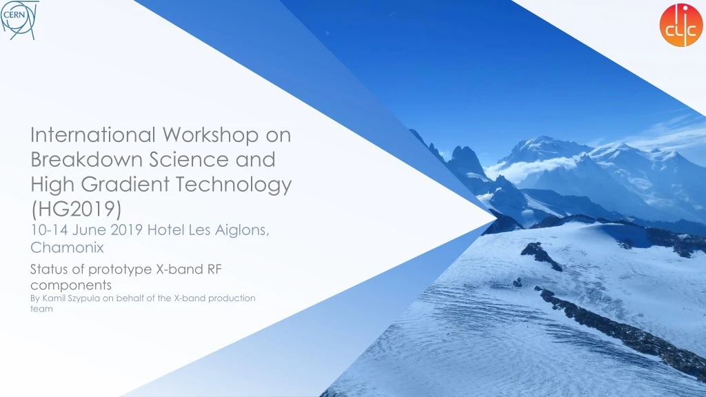
International Workshop on Breakdown Science and High Gradient Technology (HG2019)10-14 June 2019Hotel Les Aiglons, Chamonix Status of prototype X-band RF components By Kamil Szypula on behalf of the X-band production team
Agenda 3D printed spiral loads RF window Modeconverter Phaseshifterinvestigation Other components OHL Cooperatingproviders HG 2019 14/6/2019
FIRST DEVELOPMENTS Mechanical Design RF Design Manufactured in Stainless Steel Manufactured at 3T and tested in Xbox3 Manufactured by Initial Later cut with EDM Manufactured at CERN and tested in Xbox3 Manufactured in Titanium
CURRENT DEVELOPMENTS Mechanical Design RF Design Two manufactured at CERN in TitaniumOne tested in Airbus Two manufactured at 3T in Titanium Two manufactured at CERN in Stainless Steel
SUMMARISING DIAGRAM OF LOW POWER TESTS Courtesy of H. Bursali
SUMMARISING TABLE OF MANUFACTURED SPIRAL LOADS Credits to V.del Pozo Romano, N. CatalanLasheras, A.Grudiev. B.Mena
FUTURE STEPS Our motivations The current design works Yet the design is not optimised for 3D printing A cross section of the current 3D printed loads We aim to maximize the output and therefore minimise the costs We create a first a optimised mechanical 3D model first and then check the RF parameters A proposed cross section for additive manufacturing optimisation
RF WINDOW& MODE CONVERTERCONSIDERATIONS An RF windowserves as a barier between the vacuumside and the outputtransmissionline The windowmustwithstand high power, thermal and mechanicalstresses A peakpower of 75[MW] has to be considered Electric field at the ceramicwindowshould be lowerthan 3.4[MV/m],therefore the diameterhasbeendesignedat 65[mm] of diameter The modeconverterfeatures atransition of TE10mode(double height rectangular waveguide)to a TE01mode(circular waveguide) The componentswill be manufacturedat CERN using OFE copper as well as alumininaceramics For each of the RF windowstwomodeconvertersareplanned
RF WINDOWDEVELOPMENT Mechanical design & drawings RF Design RF cavities MechanicalSimulations Window pillbox Courtesy of C. Serpico, I. Syratchev, M.Aicheler, M. Capstick
RF WINDOWASSEMBLY The assembly of cooper sleeve creates the cooling channel Brazing channels Tungsten wire to be usedduring the brazing EBW lips The ceramicismetalised with a 20[μm]layer to avoid multipactoring Brazing of Alumina ceramic to the machined copper sleeve Brazing of EBW cooper ring to double knife CF flange EBW of the pillbox The twosymmetrical RF cavities are sandwitchedwith the pillbox Brazing in one step of CF flanges with the RF cavity Full assembly of the RF window
RF WINDOW STRESS AND THERMAL SIMULATIONS Thermal and stresssimulationshavebeenconducted to calculate the maximum temperature and deflection on the ceramics window Maximum deflection on the ceramic: 9,1[μm] Maximum temperature on the ceramic: 65,88 [oC] ΔΤof coolant: 0,01[oC] Water flow thermal simulations A simulation including RF characteristics, thermal and stress will be conducted as well Courtesy of M.Aicheler, M. Capstick
MODE CONVERTERDEVELOPMENT Mechanical design & drawings RF Design Courtesy of C. Serpico, I. Syratchev. A. Grudiev
MODE CONVERTERASSEMBLY Brazing of the bodies and the machining of theirinterfaces Machining of the body parts Machining of the body parts Brazing of the doubleheight WR90 flange with the modeconverter body
MODE CONVERTERASSEMBLY Brazing of the cylinder circular waveguide, with the body of the mode converter Au/Cu alloy to be used during brazing The configuration of the brazing steps is subject to change
FUTURE STEPS Ceramic discs have arrived and have been nickel and silver plated A total of sixmodeconverters as well as three RF windows. To be manufactured and assembledat CERN As the mechanicaldevelopmentshavefinished, the manufacturingis set to start soon
PHASE SHIFTERINVESTIGATION Visible burns on the piston Design in use Endoscopyimages Courtesy of L. Millar
PHASE SHIFTER INVESTIGATION Redesignedmovableshort piece Use of existing drive mechanism and a piston modification Develop a solution to stop the overheating of the drive
OTHER COMPONENTS Directional coupler/One received as qualification part High power load/ One received as qualification part Power splitter Compact pumping port
OHL What is OHL? OHL is an open repository with the most common X-band components for use in high power facilities The repository possess the technical drawings and step files of the components Anybody with granted access may use the components for fabrication Any changes must be reported https://espace.cern.ch/project-clic-xband-production/_layouts/15/start.aspx#/Open%20Hardware%20Xband%20components/Forms/AllItems.aspx
CONCLUSIONS A total of 9 spiral loadshavebeenmanufactured, 6 of them most recently with the newest design The X-band window and the modeconverterare set to be produced by the end of thisyear The phaseshifterproblem will be an issue for more investigation A numer of othercomponentshasbeenmanufactured as part of qualification A repository of componentsavailable for cooperatorshasbeenestablished
THANK YOU FOR YOUR ATTENTION With specialthanks to Nuria, Anastasiya, Joel, Enrique, Hikmet, Sergio, Serge, Markus, Matthew and all of the X-boxes team! Kamil Szypula CERN kamil.szypula@cern.ch +41227662302