Download
1 / 13
130 likes | 218 Views
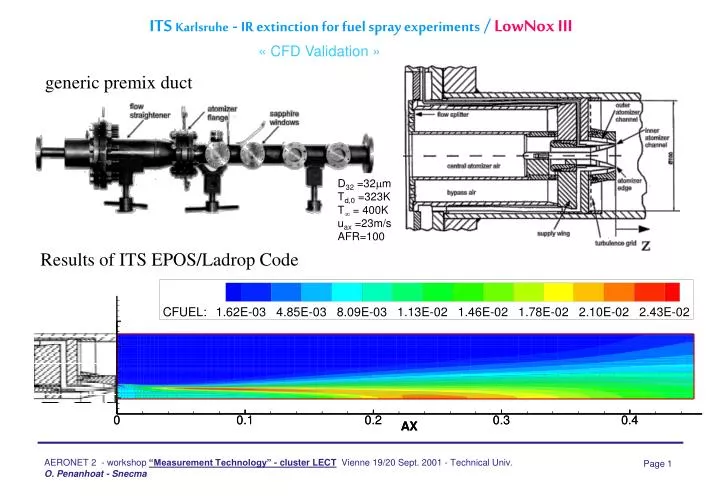
ITS Karlsruhe - IR extinction for fuel spray experiments / LowNox III. « CFD Validation ». generic premix duct. D 32 =32 m T d,0 =323K T = 400K u ax =23m/s AFR=100. Results of ITS EPOS/Ladrop Code. DLR - LDA and CARS for RQL combustor analysis / LowNox III. LDA.

E N D
ITS Karlsruhe - IR extinction for fuel spray experiments / LowNox III « CFD Validation » generic premix duct D32 =32m Td,0 =323K T = 400K uax =23m/s AFR=100 Results of ITS EPOS/Ladrop Code
DLR - LDA and CARS for RQL combustor analysis / LowNox III LDA
D : x=x1 O : x=x2 filled symbols: wake open symbols:passage Figure 2. Radial profiles of axial and tangential air velocity and of turbulent kinetic energy (LDA) Figure 1. Schematic of test section (not to scale). White arrow indicates position and orientation offuel nozzle. DLR - PDA and LDA for spray dispersion / LowNox III
ENSMA - LIF and LDV measurements / LOWNOXIII « THALIE rig » Hot burned gases • realistic experimental conditions andlarge variation range • stability, reliability and reproducibility of the experiments (PID controllers) • wide range of metrology used • computer monitored • accuracy of measurements RIG ALSO used in LOPOCOTEP
ENSMA - Optical measurements / LOWNOXIII « THALIE rig » dt = 10 ns Planar Laser Induced Fluorescence - acetone (280 nm) - - Average image 241 inst.
Cranfield - 1 bar optical spray rig / ICLEAC Possible upgrade to 3 bar in Icleac
Spray Laser Light sheet illuminates a plane Intensified CCD camera Cranfield - Measurement techniques for instabilitites / ICLEAC • Laser Sheet Drop sizing, LIF imaging and Mie imaging • - produce calibrated images of fuel concentration and SMD • - imaging method - ie data acquired simultaneously at 10 points in a plane • - take images at a number of different phases in the acoustic cycle and show the cyclic behaviour • - phase-lock averaging : take e.g. 100 images at the same phase in consecutive cycles and average to • reduce statistical fluctuations and random errors • Phase Doppler Anemometry (PDA) • - point measurement of dropsize distribution and velocity distribution • -time resolved • - can be used to deduce the airvelocity with fuel present • Particle Image Velocimetry (PIV) and Laser Doppler Anemometry (LDA) • - imaging / point methods for measuring air velocity • - time resolved measurements and phase lock averaging possible
Cranfield - LIF & Mie Scattering on fuel jet / ICLEAC LIF : Camera is filtered to see only fluorescence from dyed fuel; local intensity is proportional to local fuel concentration 100 individual images are averaged to give a mean image (statistical fluctuations removed) Individual images (pixels intensity represented on a false colour scale)
Cranfield - LIF & Mie Scattering on fuel jet / ICLEAC Mie : Camera is filtered to see only Mie Scattered light (droplet surface reflected) 100 individual images are averaged to give a mean image (statistical fluctuations removed) Individual images (pixels intensity represented on a false colour scale)
Cranfield - LIF & Mie Scattering on fuel jet / ICLEAC LSD : dropsize map (Laser Sheet Dropsizing) = mean LIF image divided by mean Mie image ; local intensity proportional to Sauter Mean Diameter
Onera - Laser based methods / VATELEC « Non intrusive measurements in LPP combustors and cooling devices » See Vatelec slides attached
Cluster Low Emission Cpmbustor Technology « SYNERGY BETWEEN PROGRAMMES FOR MEASUREMENTS PS : MATRIX TO BE COMPLETED and VALIDATED !
Cluster Low Emission Cpmbustor Technology CONCLUSION & PERSPECTIVES • Effort to improve measurement techniques and definition of rigorous procedures. • Platform with instrumentation dedicated to a real combustor. • Need of a better evaluation of radiative fluxes for thermal balances • Strong need to apply non intrusive measurements inside real combustors to measure • temperature fields, drop size distribution, Nox field, soots field …(to be completed) • => Better physical comprehension and CFD validation • => Greater ability to design low emission combustors • what are the most promising methods for this objective : CARS ? ...