Download
1 / 65
650 likes | 832 Views
Chapters 6-7 Object-Oriented Software Engineering: Using UML, Patterns, and Java, 2 nd Edition By B. Bruegge and A. Dutoit Prentice Hall, 2004. System Design. Overview. System Design 1. Identifying Design Goals 2. Mapping Objects to Subsystems 3. Hardware/Software Mapping

E N D
Chapters 6-7 Object-Oriented Software Engineering: Using UML, Patterns, and Java, 2nd Edition By B. Bruegge and A. Dutoit Prentice Hall, 2004. System Design
Overview • System Design 1. Identifying Design Goals 2. Mapping Objects to Subsystems 3. Hardware/Software Mapping 4. Persistent Data Management 5. Global Resource Handling and Access Control 6. Software Control and Concurrency 7. Boundary Conditions • Practical Matters
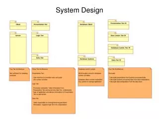
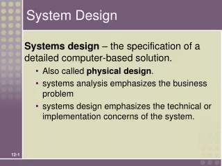
System Design • Tells the customer what the system will do • Where will the data come from? • What will happen to the data in the system? • What will the system look like to users? • What choices will be offered to users? • What is the timing of events? • What will the reports and screens look like? • Tells the programmers what the system will do • major hardware components and their function • hierarchy and functions of software components • data structures • data flow
How to use the results from the Requirements Analysis for System Design • Nonfunctional requirements => • Activity 1: Design Goals Definition • Functional model => • Activity 2: System decomposition (Selection of subsystems based on functional requirements, cohesion, and coupling) • Object model => • Activity 4: Hardware/software mapping • Activity 5: Persistent data management • Dynamic model => • Activity 3: Concurrency • Activity 6: Global resource handling • Activity 7: Software control • Subsystem Decomposition • Activity 8: Boundary conditions
Identifying Design Goals • Prioritize criteria • Performance • Response time, throughput, memory • Dependability • Robustness, reliability, availability, fault tolerance, security, safety • Cost • Cost of development, deployment, upgrading, maintenance, administration • Maintenance • Extensibility, modifiability, adaptability, portability, readability, traceability of requirements • End user • Utility, usability • Tradeoffs are decided at this point
Typical Design Trade-offs • Functionality vs. Usability • Cost vs. Robustness • Efficiency vs. Portability • Rapid development vs. Functionality • Cost vs. Reusability • Backward Compatibility vs. Readability
Overview • System Design 1. Identifying Design Goals 2. Mapping Objects to Subsystems 3. Hardware/Software Mapping 4. Persistent Data Management 5. Global Resource Handling and Access Control 6. Software Control and Concurrency 7. Boundary Conditions • Practical Matters
Subsystem Decomposition • Identification of subsystems, services and their relationship to each other and to the environment. • In object-oriented design, this consists of: • Defining the software architecture (see Ch. 11 of Sommerville book) • Mapping analysis objects into the architecture’s subsystems. • Should show correspondence between requirements and elements of the constructed system. • Should address emergent, non-functional requirements by satisfying design goals.
Subsystems and Services • Subsystem (UML: Package) • Collection of classes, associations, operations, events and constraints that are interrelated • Seed for subsystems: UML Objects and Classes. • (Subsystem) Service: • Group of operations provided by the subsystem • Seed for services: Subsystem use cases • Service is specified by Subsystem interface: • Specifies interaction and information flow from/to subsystem boundaries, but not inside the subsystem. • Should be well-defined and small. • Often called API: Application programmer’s interface, but this term should used during implementation, not during System Design
Services and Subsystem Interfaces • Service: A set of related operations that share a common purpose • Notification subsystem service: • LookupChannel() • SubscribeToChannel() • SendNotice() • UnscubscribeFromChannel() • Services are defined in System Design • Subsystem Interface: Set of fully typed related operations. • Subsystem Interfaces are defined in Object Design • Also called application programmer interface (API)
Identifying Subsystems • Heuristics • Assign objects identified in one use case into the same subsystem • Create a dedicated subsystem for objects used for moving data among subsystems • Minimize the number of associations crossing subsystem boundaries • All objects in the same subsystem should be functionally related
Coupling and Cohesion • Goal: Reduction of complexity while change occurs • Cohesion measures the dependence among classes • High cohesion: The classes in the subsystem perform similar tasks and are related to each other (via associations) • Low cohesion: Lots of miscellaneous and auxiliary classes, no associations • Coupling measures dependencies between subsystems • High coupling: Changes to one subsystem will have high impact on the other subsystem (change of model, massive recompilation, etc.) • Low coupling: A change in one subsystem does not affect any other subsystem • Subsystems should have as maximum cohesion and minimum coupling as possible: • How can we achieve high cohesion? • How can we achieve loose coupling?
Example of reducing the coupling of subsystems. Alternative 1: Direct access to the Database subsystem ResourceManagement IncidentManagement MapManagement Database Subsystem boundary
Example of reducing the coupling of subsystems (continued) Alternative 2: Indirect access to the Database through a Storage subsystem ResourceManagement IncidentManagement MapManagement Storage Subsystem boundary Database
Choosing Subsystems • Criteria for subsystem selection: Most of the interaction should be within subsystems, rather than across subsystem boundaries (High cohesion). • Does one subsystem always call the other for the service? • Which of the subsystems call each other for service? • Primary Question: • What kind of service is provided by the subsystems (subsystem interface)? • Secondary Question: • Can the subsystems be hierarchically ordered (layers)? • What kind of model is good for describing layers and partitions?
Partitions and Layers • Partitioning and layering are techniques to achieve low coupling. • A large system is usually decomposed into subsystems using both, layers and partitions. • Partitions vertically divide a system into several independent (or weakly-coupled) subsystems that provide services on the same level of abstraction. • Partitions are usually functional divisions • A layer is a subsystem that provides subsystem services to a higher layers (level of abstraction) • A layer can only depend on lower layers • A layer has no knowledge of higher layers
Relationships between Subsystems • Layer relationship • Layer A “Calls” Layer B (runtime) • Layer A “Depends on” Layer B (“make” dependency, compile time) • Partition relationship • The subsystems have mutual but not deep knowledge about each other • Partition A “Calls” partition B and partition B “Calls” partition A
Overview • System Design 1. Identifying Design Goals 2. Mapping Objects to Subsystems 3. Hardware/Software Mapping 4. Persistent Data Management 5. Global Resource Handling and Access Control 6. Software Control and Concurrency 7. Boundary Conditions • Practical Matters
Hardware-Software Mapping • This activity addresses two questions: • How shall we realize the subsystems: Hardware or Software? • How is the object model mapped on the chosen hardware & software? • Mapping Objects onto Reality: Processor, Memory, Input/Output • Mapping Associations onto Reality: Connectivity • Hardware and software selection • Also includes selecting the virtual machine (OS, protocol stacks, middleware, etc.) • Much of the difficulty of designing a system comes from meeting externally-imposed hardware and software constraints. • Certain tasks have to be at specific locations
Drawing Hardware/Software Mappings in UML • System design must model static and dynamic structures: • Component Diagrams for static structures • show the structure at design time or compilation time • Deployment Diagram for dynamic structures • show the structure of the run-time system
Component Diagram • Component Diagram • A graph of components connected by dependency relationships. • Shows the dependencies among software components • source code, linkable libraries, executables • Dependencies are shown as dashed arrows from the client component to the supplier component. • The kinds of dependencies are implementation language specific. • A component diagram may also be used to show dependencies on a façade: • Use dashed arrow the corresponding UML interface.
Scheduler Planner GUI Component Diagram Example reservations UML Component UML Interface update
Deployment Diagram • Deployment diagrams are useful for showing a system design after the following decisions are made • Subsystem decomposition • Concurrency • Hardware/Software Mapping • A deployment diagram is a graph of nodes connected by communication associations. • Nodes are shown as 3-D boxes. • Nodes may contain component instances. • Components may contain objects (indicating that the object is part of the component)
:Planner :Scheduler :HostMachine <<database>> meetingsDB :PC Deployment Diagram Example Compile Time Dependency Runtime Dependency
Mapping the Objects to Nodes • Processor issues: • Is the computation rate too demanding for a single processor? • Can we get a speedup by distributing tasks across several processors? • How many processors are required to maintain steady state load? • Memory issues: • Is there enough memory to buffer bursts of requests? • I/O issues: • Do you need an extra piece of hardware to handle the data generation rate? • Does the response time exceed the available communication bandwidth between subsystems or a task and a piece of hardware?
Mapping the Subsystems Associations: Connectivity • Describe the physical connectivity of the hardware • Often the physical layer in ISO’s OSI Reference Model • Which associations in the object model are mapped to physical connections? • Which of the client-supplier relationships in the analysis/design model correspond to physical connections? • Describe the logical connectivity (subsystem associations) • Identify associations that do not directly map into physical connections: • How should these associations be implemented?
Typical Informal Example of a Connectivity Drawing Physical Connectivity TCP/IP Ethernet Logical Connectivity
Application Object Presentation CORBA Session Transport Socket TCP/IP Network DataLink Physical Ethernet Wire Middleware can also provide logical connectivity
Subsystem 1 Subsystem 2 Layer 1 Layer 2 Layer 1 Layer 2 Layer 3 Layer 3 Layer 4 Application Layer Application Layer Presentation Layer Presentation Layer Session Layer Session Layer Bidirectional associa- tions for each layer Transport Layer Transport Layer Network Layer Network Layer Data Link Layer Data Link Layer Hardware Hardware Processor 1 Processor 2
Hardware/Software Mapping Questions • What is the connectivity among physical units? • Tree, star, matrix, ring • What is the appropriate communication protocol between the subsystems? • Function of required bandwidth, latency and desired reliability, desired quality of service (QOS) • Is certain functionality already available in hardware? • Do certain tasks require specific locations to control the hardware or to permit concurrent operation? • Often true for embedded systems • General system performance question: • What is the desired response time?
Connectivity in Distributed Systems • If the architecture is distributed, we need to describe the network architecture (communication subsystem) as well. • Questions to ask • What are the transmission media? (Ethernet, Wireless) • What is the Quality of Service (QOS)? What kind of communication protocols can be used? • Should the interaction asynchronous, synchronous or blocking? • What are the available bandwidth requirements between the subsystems? • Stock Price Change -> Broker • Icy Road Detector -> ABS System
Overview • System Design 1. Identifying Design Goals 2. Mapping Objects to Subsystems 3. Hardware/Software Mapping 4. Persistent Data Management 5. Global Resource Handling and Access Control 6. Software Control and Concurrency 7. Boundary Conditions • Practical Matters
Persistent Data Management • Some objects in the models need to be persistent • Candidates: entity objects, others as well • Anything that outlives its use case • Anything that must survive a system shutdown or crash • Can lead to new subsystems dedicated to managing persistent data • Provide clean separation points between subsystems with well-defined interfaces. • A persistent object can be realized with one of the following • Data structure • If the data can be volatile • Files • Cheap, simple, permanent storage • Low level (Read, Write) • Applications must add code to provide suitable level of abstraction • Database • Powerful, easy to port • Supports multiple writers and readers
File or Database? • When should you choose a file? • Are the data voluminous (bit maps)? • Do you have lots of raw data (core dump, event trace)? • Do you need to keep the data only for a short time? • Is the information density low (archival files,history logs)? • When should you choose a database? • Do the data require access at fine levels of details by multiple users? • Must the data be ported across multiple platforms (heterogeneous systems)? • Do multiple application programs access the data? • Does the data management require a lot of infrastructure?
Object-Oriented Databases • Support all fundamental object modeling concepts • Classes, Attributes, Methods, Associations, Inheritance • Mapping an object model to an OO-database • Determine which objects are persistent. • Perform normal requirement analysis and object design • Create single attribute indices to reduce performance bottlenecks • Do the mapping (specific to commercially available product). Example: • In ObjectStore, implement classes and associations by preparing C++ declarations for each class and each association in the object model • When to use • Complex data relationships, medium-size dataset
Relational Databases • Based on relational algebra • Data is presented as 2-dimensional tables. Tables have a specific number of columns and and arbitrary numbers of rows • Primary key: Combination of attributes that uniquely identify a row in a table. Each table should have only one primary key • Foreign key: Reference to a primary key in another table • SQL is the standard language defining and manipulating tables. • Leading commercial databases support constraints. • Referential integrity, for example, means that references to entries in other tables actually exist. • When to use • Complex queries, large dataset
Compromise: Object-Relational Mapping • Provides abstraction that maps objects to relational tables. • Developer only deals with objects. • Persistent objects are mapped to relational tables. • Access to persistent objects are mapped to database accesses. • O/R mapping layer hides these operations from OO developer.
RouteAssistant PlanningService Trip Location Direction Destination Crossing Segment Example: MyTrip route planning and executionAnalysis Object Model
PlanningSubsystem RoutingSubsystem RouteAssistant PlanningService Trip Location Direction Destination Crossing Segment Initial subsystem decomposition for MyTrip
:OnBoardComputer :WebServer PlanningSubsystem RoutingSubsystem Allocation of MyTrip subsystems to hardware.
PlanningSubsystem RoutingSubsystem RouteAssistant PlanningService Trip Location Destination TripProxy Direction Crossing SegmentProxy Segment CommunicationSubsystem Message Connection Revised design model for MyTrip. Additional objects added due to hardware distribution.
RoutingSubsystem PlanningSubsystem CommunicationSubsystem TripFileStoreSubsystem MapDBStoreSubsystem Addition of Persistent Data Storage Subsystems to MyTrip
Overview • System Design 1. Identifying Design Goals 2. Mapping Objects to Subsystems 3. Hardware/Software Mapping 4. Persistent Data Management 5. Global Resource Handling and Access Control 6. Software Control and Concurrency 7. Boundary Conditions • Practical Matters
Global Resource Handling • Discusses access control • Describes access rights for different classes of actors • Describes how objects guard against unauthorized access
Defining Access Control • In multi-user systems different actors have access to different functionality and data. • During analysis we model these different accesses by associating different use cases with different actors. • During system design we model these different accesses by examining the object model and determining which objects are shared among actors. • Depending on the security requirements of the system, we also define how actors are authenticated to the system and how selected data in the system should be encrypted.
Access Matrix • We model access on classes with an access matrix. • The rows of the matrix represents the actors of the system • The column represent classes whose access we want to control. • Access Right: An entry in the access matrix. It lists the operations that can be executed on instances of the class by the actor.
Access Matrix Implementations • Global access table: Represents explicitly every cell in the matrix as a (actor, class, operation) tuple. • Determining if an actor has access to a specific object requires looking up the corresponding tuple. If no such tuple is found, access is denied. • Access control list associates a list of (actor, operation) pairs with each class to be accessed. • Every time an object is accessed, its access list is checked for the corresponding actor and operation. • Example: guest list for a party. • A capability associates a (class, operation) pair with an actor. • A capability provides an actor to gain control access to an object of the class described in the capability. • Example: An invitation card for a party. • Which is the right implementation?
Global Resource Access Questions • Does the system need authentication? • If yes, what is the authentication scheme? • User name and password? Access control list • Tickets? Capability-based • What is the user interface for authentication? • Does the system need a network-wide name server? • How is a service known to the rest of the system? • At runtime? At compile time? • By port? • By name?
Overview • System Design 1. Identifying Design Goals 2. Mapping Objects to Subsystems 3. Hardware/Software Mapping 4. Persistent Data Management 5. Global Resource Handling and Access Control 6. Software Control and Concurrency 7. Boundary Conditions • Practical Matters
Centralized vs. Decentralized Designs • Should you use a centralized or decentralized design? • Take the sequence diagrams and control objects from the analysis model • Check the participation of the control objects in the sequence diagrams • If sequence diagram looks more like a fork: Centralized design • The sequence diagram looks more like a stair: Decentralized design • Centralized Design • One control object or subsystem ("spider") controls everything • Pro: Change in the control structure is very easy • Con: The single control object is a possible performance bottleneck • Decentralized Design • Not a single object is in control, control is distributed • Con: The responsibility is spread out • Pro: Fits nicely into object-oriented development