Download
1 / 311
3.14k likes | 3.26k Views
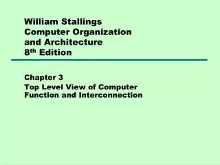
EE3004 (EE3.cma) - Computer Architecture. Roger Webb R.Webb@surrey.ac.uk University of Surrey http://www.ee.surrey.ac.uk/Personal/R.Webb/l3a15 also link from Teaching/Course page. Book List Computer Architecture - Design & Performance Barry Wilkinson, Prentice-Hall 1996

E N D
EE3004 (EE3.cma) - Computer Architecture Roger Webb R.Webb@surrey.ac.uk University of Surrey http://www.ee.surrey.ac.uk/Personal/R.Webb/l3a15 also link from Teaching/Course page EE3.cma - Computer Architecture
Book List Computer Architecture - Design & Performance Barry Wilkinson, Prentice-Hall 1996 (nearest to course) Advanced Computer Architecture Richard Y. Kain, Prentice-Hall 1996 (good for multiprocessing + chips + memory) Computer Architecture Behrooz Parhami, Oxford Univ Press, 2005 (good for advanced architecture and Basics) Computer Architecture Dowsing & Woodhouse (good for putting the bits together..) Microprocessors & Microcomputers - Hardware & Software Ambosio & Lastowski (good for DRAM, SRAM timing diagrams etc.) Computer Architecture & Design Van de Goor (for basic Computer Architecture) Wikipedia is as good as anything...! Introduction EE3.cma - Computer Architecture
Outline Syllabus Memory Topics Memory Devices Interfacing/Graphics Virtual Memory Caches & Hierarchies Instruction Sets Properties & Characteristics Examples RISC v CISC Pipelining & Concurrency Parallel Architectures Performance Characteristics SIMD (vector) processors MIMD (message-passing) Principles & Algorithms Introduction EE3.cma - Computer Architecture
What are computers used for? 3 ranges of product cover the majority of processor sales: Appliances (consumer electronics) Communications Equipment Utilities (conventional computer systems) Computer Architectures - an overview EE3.cma - Computer Architecture
Computer Architectures - an overview Consumer Electronics This category covers a huge range of processor performance • Micro-controlled appliances • washing machines, time switches, lamp dimers • lower end, characterised by: • low processing requirements • microprocessor replaces logic in small package • low power requirements • Higher Performance Applications • Mobile phones, printers, fax machines, cameras, games consoles, GPS, TV set-top boxes, video/DVD/HD recorders…... • High bandwidth - 64-bit data bus • Low power - to avoid cooling • Low cost - < $20 for the processor • Small amounts of software - small cache (tight program loops) EE3.cma - Computer Architecture
Computer Architectures - an overview Communications Equipment has become the major market – WWW, mobile comms • Main products containing powerful processors are: • LAN products - bridges, routers, controllers in computers • ATM exchanges • Satellite & Cable TV routing and switching • Telephone networks (all-digital) • The main characteristics of these devices are: • Standardised application (IEEE, CCITT etc.) - means competitive markets • High bandwidth interconnections • Wide processor buses - 32 or 64 bits • Multi-processing (either per-box, or in the distributed computing sense EE3.cma - Computer Architecture
Computer Architectures - an overview Utilities (Conventional Computer Systems) Large scale computing devices will, to some extent, be replaced by greater processing power on the desk-top. • But some centralised facilities are still required, especially where data storage is concerned • General-purpose computer servers; supercomputers • Database servers - often safer to maintain a central corporate database • File and printer servers - again simpler to maintain • Video on demand servers • These applications are characterised by huge memory requirements and: • Large operating systems • High sustained performance over wide workload variations • Scalability - as workload increases • 64 bit (or greater) data paths, multiprocessing, large caches EE3.cma - Computer Architecture
Computer Architectures - an overview Computer System Performance • Most manufacturers quote performance of their processors in terms of the peak rate - MIPS (MOPS) of MFLOPS. • Most of the applications above depend on the continuous supply of data or results - especially for video images • Thus critical criterion is the sustained throughput of instructions • (MPEG image decompression algorithm requires 1 billion operations per second for full-quality widescreen TV) • Less demanding VHS quality requires 2.7Mb per second of compressed data • Interactive simulations (games etc) must respond to a user input within 100ms - re-computing and displaying the new image • Important measures are: • MIPS per dollar • MIPS per Watt EE3.cma - Computer Architecture
Computer Architectures - an overview Virtual Reality, Cyberspace WYSIWIG, Mice, Windows Menus, Forms Timesharing Punched Card & Tape Lights & Switches User Interactions Consider how we interact with our computers: What does a typical CPU do? 70% User interface; I/O processing 20% Network interface; protocols 9% Operating system; system calls 1% User application % of CPU time spent managing interaction EE3.cma - Computer Architecture
Computer Architectures - an overview Sequential Processor Efficiency The current state-of-the-art of large microprocessors include: • 64-bit memory words, using interleaved memory • Pipelined instructions • Multiple functional units (integer, floating point, memory fetch/store) • 5 GHz practical maximum clock speed • Multiple processors • Instruction set organised for simple decoding (RISC?) However as word length increases, efficiency may drop: • many operands are small (16 bit is enough for many VR tasks) • many literals are small - loading 00….00101 as 64 bits is a waste • may be worth operating on several literals per word in parallel EE3.cma - Computer Architecture
Computer Architectures - an overview x y z 1 a b c d e f g h i j k l m n o p x’ y’ z’ r Example - reducing the number of instructions Perform a 3D transformation of a point (x,y,z) by multiplying the 4-element matrix (x,y,z,1) by a 4x4 transformation matrix A. All operands are 16-bits long. = Conventionally this requires 20 loads, 16 multiplies, 12 adds and 4 stores, using 16-bit operands on a 16-bit CPU. On a 64-bit CPU with instructions dealing with groups of four parallel 16-bit operands, as well as a modest amount of pipelining, all this can take just 7 processor cycles. EE3.cma - Computer Architecture
Computer Architectures - an overview memory memory memory memory cache Interconnection Network CPU CPU CPU CPU The Effect of Processor Intercommunication Latency In a multiprocessor, and even in a uniprocessor, the delays associated with communicating and fetching data (latency) can dominate the processing times. Consider: Symmetrical Multiprocessor Uniprocessor • Delays can be minimised by placing components closer together and: • Add caches to provide local data storage • Hide latency by multi-tasking - needs fast context switching • Interleave streams of independent instructions - scheduling • Run groups of independent instructions together (each ending with long latency instruction) EE3.cma - Computer Architecture
Computer Architectures - an overview Memory Efficiency Quote from 1980s “Memory is free” By the 2000s the cost per bit is no longer falling so fast and consumer electronics market is becoming cost sensitive Renewed interest in compact instruction sets and data compactness - both from the 1960s and 1970s Instruction Compactness RISC CPUs have a simple register-based instruction encoding • Can lead to codebloat - as can poor coding and compiler design • Compactness gets worse as the word size increases e.g. INMOS (1980s) transputer had a stack based register scheme • needed 60% of the code of an equivalent register based cpu • lead to smaller cache needs for instruction fetches & data 1977 - £3000/Mb 1994 - £4/Mb Now – <1p/Mb EE3.cma - Computer Architecture
Computer Architectures - an overview Cache Efficiency • Designer should aim to optimise the instruction performance whilst using the smallest cache possible • Hiding latency (using parallelism & instruction scheduling) is an effective alternative to minimising it (by using large caches) • Instruction scheduling can initiate cache pre-fetches • Switch to another thread if the cache is not ready to supply data for the current one • In video and audio processing, especially, unroll the inner code loops – loop unrolling (more on that later) EE3.cma - Computer Architecture
Computer Architectures - an overview Predictable Codes In many applications (e.g. video and audio processing) much is known about the code which will be executed. Techniques which are suitable for these circumstances include: • Partition the cache separately for code and different data structures • The cache requirements of the inner code loops can be pre-determined, so cache usage can be optimised • Control the amounts of a data structure which are cached • Prevent interference between threads by careful scheduling • Notice that a conventional cache’s contents are destroyed by a single block copy instruction EE3.cma - Computer Architecture
Computer Architectures - an overview Processor Engineering Issues • Power consumption must be minimised (to simplify on-chip and in-box cooling issues) • Use low-voltage processors (2V instead of 3.3V) • Don’t over-clock the processor • Design logic carefully to avoid propagation of redundant signals • Tolerance of latency allows lower performance (cheaper) subsystems to be used • Explicit subsystem control allows subsystems to be powered down when not in use • Eliminate redundant actions - eg speculative pre-fetching • Provide non-busy synchronisation to avoid the need for spin-locks • Battery design is advancing slowly - power stored per unit weight or volume will quadruple (over NiCd) with 5-10 years EE3.cma - Computer Architecture
Computer Architectures - an overview Processor Engineering Issues • Speed to market is increasing, so processor design is becoming critical. Consider the time for several common devices to become established: • 70 years Telephone (0% to 60% of households) • 40 years Cable Television • 20 years Personal Computer • 10 years Video Recorders • <10years Web based video • Modularity and common processor cores provide design flexibility • reusable cache and CPU cores • product-specific interfaces and co-processors • common connection schemes EE3.cma - Computer Architecture
Computer Architectures - an overview Interconnect Schemes Wide data buses are a problem: • They are difficult to route on printed circuit boards • They require huge numbers of processor and memory pins (expensive to manufacture on chips and PCBs) • Clocking must accommodate the slowest bus wire. • Parallel back-planes add to loading and capacitance, slowing signals further and increasing power consumption Serial chip interconnects offer 1Gbit/s performance using just a few pins and wires. Can we use a packet routing chip as a back-plane? • Processors, memories, graphic devices, networks, slow external interfaces all joined to a central switch EE3.cma - Computer Architecture
3 EE3.cma - Computer Architecture
Memory Devices Regardless of scale of computer the memory is similar. Two major types: • Static • Dynamic Larger memories get cheaper as production increases and smaller memories get more expensive - you pay more for less! See: http://www.educypedia.be/computer/memoryram.htm http://www.kingston.com/tools/umg/default.asp http://www.ahinc.com/hhmemory.htm EE3.cma - Computer Architecture
Memory Devices Static Memories • made from static logic elements - an array of flip-flops • don’t lose their stored contents until clocked again • may be driven as slowly as needed - useful for single stepping a processor • Any location may be read or written independently • Reading does not require a re-write afterwards • Writing data does not require the row containing it to be pre-read • No housekeeping actions are needed • The address lines are usually all supplied at the same time • Fast - 15ns was possible in Bipolar and 4-15ns in CMOS Not used anymore – too much power for little gain in speed EE3.cma - Computer Architecture
Memory Devices A0 Memory Matrix 256x256 Vcc A1 A2 A3 Gnd A4 Row Decoder A5 A6 A7 I/O0 Column I/O Input Data Control Column Decoder I/O7 A15 A8 CS2 CS1 Timing Pulse Generator OE Read Write Control WE HM6264 - 8K*8 static RAM organisation EE3.cma - Computer Architecture
Memory Devices tRC tAA tCO1 tLZ1 tHZ1 tCO2 tLZ2 tOE tOLZ tHZ2 tOHZ Data Valid tOH Address CS1 CS2 OE Dout HM6264 Read Cycle HM6264 - 8K*8 static RAM organisation EE3.cma - Computer Architecture
Memory Devices tWC OE tCW CS1 tCW CS2 tWR2 tWR1 tOHZ tDW tAW tWP tDH tAS WE Dout Address HM6264 Write Cycle Din HM6264 - 8K*8 static RAM organisation Data sampled by memory EE3.cma - Computer Architecture
Memory Devices Dynamic Memories • information stored on a capacitor - discharges with time • Only one transistor required to control - 6 for SRAM • must be refreshed (0.1-0.01 pF needs refresh every 2-8ms) • memory cells are organised so that cells can be refreshed a row at a time to minimise the time taken • row and column organisation lends itself to multiplexed row and column addresses - fewer pins on chip • Use RAS and CAS to latch row and column addresses sequentially • DRAM consumes high currents when switching transistors (1024 columns at a time). Can cause nasty voltage transients EE3.cma - Computer Architecture
Memory Devices I/O 1-4 row select Input Buffer Output Buffer OE Clock Bit Line Dynamic memory cell WE Clock R/W Switch CAS Clock Memory Array 2 Memory Array 1 Y Decoder RAS CAS CAS RAS WE OE RAS Clock X Decoder X Decoder Ai X Addrss Memory Array 3 Memory Array 4 Y Decoder Y Addrss Refresh Address Counter HM50464 - 64K*4 dynamic RAM organisation EE3.cma - Computer Architecture
Memory Devices WRITE RAS CAS OE row column valid output • Read Cycle • Dynamic memory read operation is as follows • The memory read cycle starts by setting all bit lines (columns) to a suitable sense voltage. - pre charging • Required row address is applied and a RAS (row address) is asserted • selected row is decoded and opens transistors (one per column). This dumps their capacitors charge into high feedback amplifiers which recharge the capacitors - RAS must remain low • simultaneously apply column address and set CAS. Decoded and requested bits are gated to output - goes to outside when OE is active Address HM50464 Read Cycle IO HM50464 - 64K*4 dynamic RAM organisation EE3.cma - Computer Architecture
Memory Devices WRITE RAS CAS row column Early Write Cycle Similar to the read cycle except the fall in WRITE signals time to latch input data. During the “Early Write” cycle - the WRITE falls before CAS - ensures that memory device keeps data outputs disabled (otherwise when CAS goes low they could output data!) Alternatively a “Late Write” cycle the sequence is reversed and the OE line is kept high - this can be useful in common address/data bus architectures Address HM50464 Write Cycle IO Valid Input HM50464 - 64K*4 dynamic RAM organisation EE3.cma - Computer Architecture
Memory Devices Refresh Cycle For a refresh no output is needed. A read, with a valid RAS and row address pulls the data out all we need to do is put it back again by de-asserting RAS. This needs to be repeated for all 256 rows (on the HM50464) every 4ms. There is an on chip counter which can be used to generate refresh addresses. Page Mode Access [“Fast Page Mode DRAM”] – standard DRAM The RAS cycle time is relatively long so optimisations have been made for common access patterns Row address is supplied just once and latched with RAS. Then column address are supplied and latched using CAS, data is read using WRITE or OE. CAS and column address can then be cycled to access bits in same row. The cycle ends when RAS goes high again. Care must be taken to continue to refresh the other rows of memory at the specified rate if needed HM50464 - 64K*4 dynamic RAM organisation EE3.cma - Computer Architecture
Memory Devices RAS CAS Address row col col col IO Data Data Data Page Mode DRAM access - nibble and static column mode are similar Nibble Mode Rather than supplying the second and subsequent column addresses they can be calculated by incrementing the initial address - first column address stored in register when CAS goes low then incremented and used in next low CAS transition - less common then Page Mode. Static Column Mode Column addresses are treated statically and when CAS is low the outputs are read if OE is low as well. If the column address changes the outputs change (after a propagation delay). The frequency of address changes can be higher as there is no need to have an inactive CAS time HM50464 - 64K*4 dynamic RAM organisation EE3.cma - Computer Architecture
Memory Devices RAS CAS OE Address row col col col IO Data Data Data Extended Data Out DRAM access HM50464 - 64K*4 dynamic RAM organisation Extended Data Out Mode (“EDO DRAM”) EDO DRAM is very similar to page mode access. Except that data bus outputs are controlled exclusively by the OE line. So that CAS can be taken high and low again without data from previous word being removed from data bus - so data can be latched by processor whilst new column address is being latched by memory. Overall cycle times can be shortened. EE3.cma - Computer Architecture
Memory Devices Clock Command Act NOP NOP read NOP NOP NOP NOP PChg NOP NOP Act Address row col bank row IO D0 D1 D2 D3 Activate DRAM row Read from Column no. (3 cycle latency) Read burst (4 words) Simplified SDRAM burst read access HM50464 - 64K*4 dynamic RAM organisation Synchronous DRAM (“SDRAM”) Instead of asynchronous control signals SDRAMs accept one command in each cycle. Different stages of access initiated by separate commands - initial row address, reading etc. all pipelined so that a read might not return a word for 2 or 3 cycles Bursts of accesses to sequential words within a row may be requested by issuing a burst-length command. Then, subsequent read or write request operate in units of the burst length EE3.cma - Computer Architecture
Summary DRAMs A whole row of the memory array must be read After reading the data must be re-written Writing requires the data to be read first (whole row has to be stored if only a few bits are changed) Cycle time a lot slower than static RAM Address lines are multiplexed - saves package pin count Fastest DRAM commonly available has access time of ~60ns but a cycle time of 121ns DRAMs consume more current SDRAMS replace the asynchronous control mechanisms Memory Devices EE3.cma - Computer Architecture
4 EE3.cma - Computer Architecture
Memory Interfacing Interfacing Most processors rely on external memory The unit of access is a word carried along the Data Bus Ignoring caching and virtual memory, all memory belongs to a single address space. Addresses are passed on the Address Bus Hardware devices may respond to particular addresses - Memory Mapped devices External memory is a collection of memory chips. All memory devices are joined to the same data bus Main purpose of the addressing logic is to ensure only one memory device is activated during each cycle EE3.cma - Computer Architecture
Memory Interfacing Interfacing The Data Bus has n lines - n = 8,16,32 or 64 The Address Bus has m lines - m = 16,20,24, 32 or 64 providing 2m words of memory The Address Bus is used at the beginning of a cycle and the Data Bus at the end It is therefore possible to multiplex (in time) the two buses Can create all sorts of timing complications - benefits are a reduced processor pin count, makes it relatively common Processor must tell memory subsystem what to do and when to do it Can do this either synchronously or asynchronously EE3.cma - Computer Architecture
Memory Interfacing Interfacing synchronously • processor defines the duration of a memory cycle • provides control lines for begin and end of cycle • most conventional • the durations and relationships might be determined at boot time (available in 1980’s in the INMOS transputer) asynchronously - • processor starts cycle, memory signals end of cycle • Error recovery is needed - if non-existent memory is accessed (Bus Error) EE3.cma - Computer Architecture
Memory Interfacing Interfacing synchronous memory scheme control signals • Memory system active • goes active when the processor is accessing external memory. • Used to enable the address decoding logic • provides one active chip select to a group of chips • Read Memory • says the processor is not driving the data bus • selected memory can return data to the data bus • usually connected to the output enable (OE) of memory EE3.cma - Computer Architecture
Memory Interfacing Interfacing synchronous memory scheme control signals (cont’d) • Memory Write • indicates data bus contains data which selected memory device should store • different processors use leading or trailing edges of signal to latch data into memory • Processors with data bus wider than 8 bits have separate memory write byte signal for each byte of data • Memory write lines connected to writelines of memories • Address Latch Enable (in multiplexed address machines) • tells the addressing logic when to take a copy of the address from multiplexed bus so processor can use it for data later • Memory Wait • causes processor to extend memory cycle • allows fast and slow memories to be used together without loss of speed EE3.cma - Computer Architecture
Memory Interfacing Address Blocks How do we place blocks of memory within the address space of our processor? Two methods of addressing memory: • Byte addressing • each byte has its own address • good for 8-bit mprocessors and graphics systems • if memory is 16 or 32 bits wide? • Word addressing • only address lines which number individual words • select multi-byte word • extra byte address bits retained in processor to manipulate individual byte • or use write byte control signals EE3.cma - Computer Architecture
Memory Interfacing Address Blocks How do we place blocks of memory within the address space of our processor? Often want different blocks of memory: • Particular addresses might be special: • memory mapped I/O ports • location executed first after a reset • fast on-chip memory • diagnostic or test locations • Also want • SRAM and/or DRAM in one contiguous block • memory mapped graphics screen memory • ROM for booting and low level system operation • extra locations for peripheral controller registers EE3.cma - Computer Architecture
Memory Interfacing Address Blocks How do we place blocks of memory within the address space of our processor? • Each memory block might be built from individual memory chips • address and control lines wired in parallel • data lines brought out separately to provide n bit word • Fit all the blocks together in overall address map • easier to place similar sized blocks next to each other so that they can be combined to produce 2k+1 word area • jumbling blocks of various sizes complicates address decoding • if contiguous blocks are not needed, place them at major power of 2 boundaries - eg put base of SRAM at 0, ROM half way up, lowest memory mapped peripheral at 7/8ths EE3.cma - Computer Architecture
Memory Interfacing Address Decoding address decoding logic determines which memory device to enable depending upon address • if each memory area stores contiguous words of 2k block • all memory devices in that area will have k address lines • connected (normally) to the k least-significant lines • remaining m-k examined to see if they provide most-significant (remaining) part of address of each area 3 schemes possible • Full decoding - unique decoding • All m-k bits are compared with exact values to make up full address of that block • only one block can become active EE3.cma - Computer Architecture
Memory Interfacing Address Decoding 3 schemes possible (cont’d) • Partial decoding • only decode some of m-k lines so that a number of blocks of addresses will cause a particular chip select to become active • eg ignoring one line will mean the same memory device will be accessible at places in memory map • makes decoding simpler • Non-unique decoding • connect different one of m-k lines directly to active low chip select of each memory block • can activate memory block by referencing that line • No extra logic needed • BUT can access 2 blocks at once this way…... EE3.cma - Computer Architecture
5 EE3.cma - Computer Architecture
Memory Interfacing Address Decoding - Example A processor has a 32-bit data bus. It also provides a separate 30-bit word addressed address bus, which is labelled A2 to A31 since it refers to memory initially using byte addressing, where it uses A0 and A1 as byte addressing bits. It is desired to connect 2 banks of SRAM (each built up from 128K*8 devices) and one bank of DRAM, built from 1M*4 devices, to this processor. The SRAM banks should start at the bottom of the address map, and the DRAM bank should be contiguous with the SRAM. Specify the address map and design the decoding logic. EE3.cma - Computer Architecture
Address Decoding - Example Each bank of SRAMs will require 4 devices to make up the 32 bit data bus. Each Bank of DRAMs will require 8 devices. Memory Interfacing EE3.cma - Computer Architecture
Memory Interfacing 20 address lines to all devices in parallel 17 address lines to all devices in parallel 17 address lines to all devices in parallel Address Decoding - Example CS3 CS1 CS2 CPU SRAM 128k*8 SRAM 128k*8 DRAM 1M*4 4 data lines to each device 8 data lines to each device CS1 connects to chip select on SRAM bank 0 CS2 connects to chip select on SRAM bank 1 CS3 connects to chip select on DRAM bank CS1 = A19*A20*A21*A22 CS2 =A19*A20*A21*A22 CS3 = A20+A21+A22 } }omitting all address lines A23 and above to simplify } EE3.cma - Computer Architecture
6 EE3.cma - Computer Architecture
Memory Interfacing Connecting Multiplexed Address and Data Buses There are many multiplexing schemes but let’s choose 3 processor types and 2 memory types and look at the possible interconnections: • Processor types all 8-bit data and 16 bit address: • No multiplexing - (eg Zilog Z80) • multiplexes least significant address bits with data bus (intel 8085) • multiplexes the most significant and least significant halves of address bus • Memory types: • SRAM (8k *8) - no address multiplexing • DRAM (16k*4) - with multiplexed address inputs EE3.cma - Computer Architecture