Download

1 / 22
220 likes | 238 Views
This paper discusses a method for determining impedance by simultaneously measuring the tunes of unequally charged bunches. It overcomes limitations in tune resolution and demonstrates high stability in tune measurements. The method utilizes high-resolution BPMs and has been successfully implemented at NSLS-II.

E N D
Precise Impedance Determination from Simultaneously Measured Tunes of Unequally Charged Bunches Boris Podobedov ICFA Mini-Workshop on Impedances and Beam Instabilities in Particle Accelerators, Benevento, Italy September 20, 2017
Outline and References Idea of the method Limits on tune resolution How to overcome them Measurement results Conclusions • B. Podobedov, W. Cheng, K. Ha, Y. Hidaka, J. Mead, O. Singh, K. Vetter, IPAC2016, WEOBB01 • B. Podobedov, W. Cheng, Y. Hidaka, D. Teytelman, IBIC2016, TUCL02 • Y. Hidaka, W. Cheng, B. Podobedov. NAPAC2016, MOA2CO03
From Tune Measurement to Coupling Impedance Kick factor: definition not so easy relation to impedance Slope is easy to measure Damping wiggler relation to tune shift with current dny/dI ~ -0.01/mA frev=379 kHz 2.64 nC => 1 mA kkick~ 15 kV/pC/m If we could resolve tunes to 10-6 then we get kick factors as low as 10 V/pC/m assumed 1 nC, <b> =4 m, 3 GeV
~10-7 Tune Resolution has been Demonstrated Single-shot measurement for 100 bunch low-current train Tune found from 180 BPMs Tune resolution down to 2x10⁻⁷ Damping wiggler But only for a single-shot (and low-current bunch train)
Shot-to-Shot Tune Stability is Much Poorer At NSLS-II typical (shot-to-shot) tune jitter is >10-4 (rms) This would normally preclude any sensitive measurements that rely on better tune resolution (including impedance) Five consecutive tune measurements (5 pings) Tune jumps without anyone touching the pinger or anything else in the machine
Shot-to-Shot Tune Jitter is a Common Obstacle for Z-measurements Example from ALBA LS: 120 Libera BPMs 100 acquisitions (shots) Single-shot tune rms=2.1×10⁻⁶ 100-shot tune rms=1.1 ×10⁻⁴
How to Overcome Tune Jitter and Drifts for Impedance Measurements Use a reference measurement: simultaneously kick, record turn-by-turn BPM positions, then calculate the tunes of two (or more) bunches stored in the ring. Tune difference gives Z. Must have high-resolution BPMs that are capable of accurate tune measurements. Better to have many of these BPMs, to improve the resolution further. BPMs must capable of resolving turn-by-turn positions of two (or more) individual bunches, with low-current bunch(es) used as a reference. high Qb low Qb reference (single bunch or short train) NSLS-II has BPMs that make this possible
NSLS-II: 30 cell DBA 3 GeV ring with 1 nm / 8 pm design emittances, smallest beam size 3 mm rms (y) Beam stability of paramount importance for users NSLS-II is equipped with a large number of high-performance BPMs (~200 at present) NSLS-II BPM Pickups LA-BPM SA-BPM top “SA-BPM” Real SA button assemblies are rotated around the vertical
NSLS-II BPM Receivers Original NSLS-II development (by Kurt Vetter et al.) Resolution specs of 1 mm turn-by-turn (TbT) and 200 nm in 10 kHz (FA) mode were verified with beam TbT used for injection & kicked beam studies, FA for fast orbit feedback & interlocks, SA for orbit measurements Recently added bunch-by-bunch capability (to resolve bunches within a turn)
NSLS-II BPM Signal Processing TbT X, Y, and S are obtained (in FPGA for Ops, or Matlab for studies) from ADC signals by coherent signal processing locked to revolution harmonic. Analog 500 MHz BP filter, ~20 MHz BW Digital 30 MHz BP, ~2 MHz BW “pilot tone filter” ADC ~23 samples TbT pilot tone filter ON FA 1 Turn = 310 ADC Samples = =1320 of 500 MHz RF buckets SA
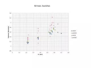
Unequal Charge Bunches Kicked with a Pinger Two-bunch fill with unequal bunches Pinger timing adjusted for equal vertical kick ADC data processed to get turn-by-turn positions for each bunch 0.75 mA 0.25 mA 0.6 turn pinger FWHM 1 turn 1 turn
Turn-by-Turn Signals Each bunch decays a long time, but the combined shows beating Also instability for high current bunch before the ping Ping on turn 20
Vertical Tunes are Distinctly Different Single BPM FFT shows tunes are clearly unequal Detailed analysis with interp’d FFT for 180 BPMs givesny=0.26833 ±1.93e-5 (bunch 1) and ny=0.26334 ± 6.90e-6 (bunch 2) Tune difference of Dn21 = -5e-3/(0.5 mA)=-0.01/ma agrees with other measurements by other methods
Same Measurement in the Horizontal Dn21 =(6.0 ± 1.9)*1e-5 Same two bunches, 0.25 mA (1) and0.75 ma (2) Use horizontal pinger BPM ADC data processed to get separate TbTs for each bunch Use 25 revolution harmonics to increase the resolution This measurement convincingly shows that horizontal tune goes up with current (i.e. total wake is slightly focussing). nx=0.22729 ± 1.71e-05 (1) nx=0.22735 ± 9.06e-06 (2) nx – 0.2271
10-6 Tune Difference Resolution Achieved Hybrid fill pattern: 1.7 mA/80 bunches + 0.35 mA camshaft (initially) Measure vert. tunes every ~3 mins Over 50 mins tune rmssn~10-4 for each Also, camshaft bunch decays by ~40 uA Tune difference, with linear part taken out, has rms=9.53×10⁻⁷ camshaft (high-Q) train (reference) snt-nc~4×10⁻⁶ 1 turn
Several measurements have been tried with promising results: Tune shift with current Probing impedance of scrapers Impedance of an empty straight section Impedance of an In-vacuum Undulator Synchrotron tune shift with current with “RF-ping” Instability studies Beam lifetime studies Single-shot tune shift with amplitude* Beam Physics Studies that Benefit from New BPM Capabilities at NSLS-II This talk *Y. Hidaka et al, Proceedings of NAPAC2016, MOA2CO03
Local Impedance Measurement: Vertical Scraper Measure tune difference between low- and high-Q bunches Repeat with the scraper inserted Change in the tune difference is due to (added) scraper impedance 1.4 mA 100 bucket train (reference) + 0.3 mA camshaft ½ ring away Complimentary measurement would be from closed orbits (no kick), TBD Dn~3 10-4 =>kkick~600 V/pC/m Blade length 1 cm Blade width 3 cm by = 26 m
Horizontal Scraper Two bunches stored, inner blade moved in Change in the tune difference is due to (added) scraper impedance With scraper blade close to the beam, tune-current slope changes to negative (agrees with expectation) Scraper in: de-focussing wake Blade length 3 cm total 45 deg tapers 1 cm ea Thickness 1.5 cm bx=19 m Scraper out: focussing wake
Measure Low-b Insertion Device Chamber Example of a fixed impedance component, use local bumps to probe Z Cell 21 has two EPUs (out-of-vacuum) Vacuum chamber is Al pipe, 4.8 m length, by0=1.2 m, resistive wall is dominates, RW kick factor 56 V/pC/m at st(0.3mA)=16.2 ps measured separately Injected 1.4 mA train + 0.3 mA camshaft Camshaft decayed some during the bumps Measured kick factor of 210 V/pC/m tune is about x4 higher than the theory for Al but is likely due to NEG coating and addl’l taper impedance
Synchrotron Tune Shift with Current RF cavity feedforward provides short (<1/fs) RF amplitude jump Beam (3 bunches, 1/3 ring apart each) is kicked longitudinally, synchrotron tune detected on dispersive BPMs (60 total) As expected, tune change with current is miniscule (imperfect cancellation of coherent and incoherent tuneshifts), yet measurable to be around 10-5/mA with this method ...
Conclusions and Future Plans We proposed fast and precise technique for measuring the transverse impedance (kick factor) of storage ring elements. The technique, enabled by state-of-the-art NSLS-II BPM receivers, derives from the ability to very accurately resolve betatron tunes of several individual bunches simultaneously stored in the ring. This 10-6 tune resolution has been successfully demonstrated. This reference technique eliminates harmful effects of machine drifts. It also eliminates other large systematic effects, unrelated to the impedance, i.e. singe particle tune change due to undulator gap closure. BPM signal processing is presently done off-line but is being implemented in FPGA. Then the improved resolution and multi-bunch capability will be available in real time greatly speeding up these measurements as well as enabling orbit-based Z-measurements. Thank you
Acknowledgements I would like to acknowledge the enormous help I received from many present and NSLS-II colleagues but especially from Weixing Cheng and Yoshi Hidaka (physics), Kiman Ha, Joe Mead, Om Singh, Kurt Vetter (diagnostics), as well as from Dmitry Teytelman, from Dimtel, (everything)