Download
1 / 29
300 likes | 446 Views
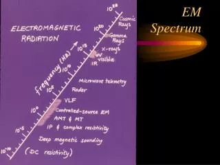
24.7 The Spectrum of EM Waves. According to wavelength or frequency, the EM waves can be distinguished into various types. There is no sharp boundary between one kind of EM wave and the next All types of the EM radiations are produced by the same phenomenon – accelerating charges.

E N D
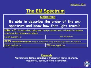
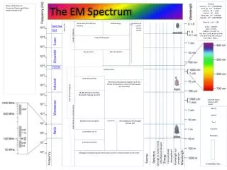
24.7 The Spectrum of EM Waves • According to wavelength or frequency, the EM waves can be distinguished into various types. • There is no sharp boundary between one kind of EM wave and the next • All types of the EM radiations are produced by the same phenomenon – accelerating charges
Long-wavelength EM Waves • Radio Waves • Wavelengths of more than 104 m to about 0.1 m • Generated by accelerating electrons in conducting wire, such as electronic devices in LC circuit • Used in radio and television communication systems • Microwaves (short-wavelength radio waves) • Wavelengths from about 0.3 m to 1 mm • Well suited for radar systems • Microwave ovens are an application
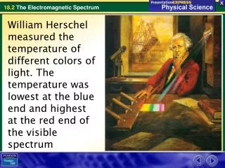
Infrared Waves and Visible light • Infrared waves • Wavelengths of about 10-3 m to 7 x 10⁻⁷ m • Produced by objects and molecules at room temperatures and readily absorbed by most materials • Vibrational sprectra of molecules, Remote control • Visible light • Wavelength of about 7 x 10⁻⁷ m to 4 x 10⁻⁷ m • Detected by the human eye • Most sensitive at about 5.5 x 10⁻⁷ m (yellow-green)
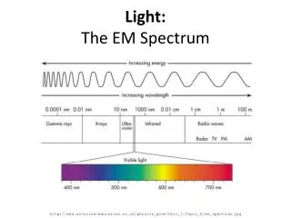
More About Visible Light • Different wavelengths correspond to different colors • The range is from red (l ~7 x 10⁻⁷ m) to violet (l ~4 x 10⁻⁷ m)
Ultraviolet light and X-rays • Ultraviolet (UV) light • Wavelength covers about 4 x 10⁻⁷ m to 6 x10⁻¹⁰ m • Sun is an important source of UV light • Most UV light from the Sun is absorbed in the stratosphere by ozone (O3) • X-rays • Wavelengths of about 10-8 m to 10-12 m • Most common source is acceleration of high-energy electrons bombarding a metal target • Used as a diagnostic tool in medicine • Wavelengths are compared to the separation distances of atoms in solids • Studying crystal and protein structures
Gamma rays • Gamma rays • Wavelengths of about 10-10m to 10-14 m • Emitted by radioactive nuclei and cosmic rays • Highly penetrating and cause serious damage when absorbed by living tissue • Looking at objects in different portions of the spectrum can produce different information
Wavelengths and Information • These are images of the Crab Nebula • They are (clockwise from upper left) taken with • x-rays • visible light • radio waves • infrared waves
24.8 Polarization of Light Waves • The E and B vectors associated with an EM wave are perpendicular to each other and to the direction of wave propagation • Polarization is a property that specifies the directions of the E and B fields associated with an EM wave • The direction of polarization is defined to be the direction in which the electric field is vibrating
Unpolarized Light • All directions of vibration from a wave source are possible • The resultant EM wave is a superposition of waves vibrating in many different directions • This is an example of the unpolarized wave • The arrows show a few possible directions of the waves in the beam
Linearly Polarization of Light • A wave is said to be linearly polarized if the resultant electric field vibrates in the same direction at all times at a particular point • The plane formed by the electric field and the direction of propagation is called the plane of polarization of the wave
Methods of Polarization • It is possible to obtain a linearly polarized beam from an unpolarized beam by removing all waves from the beam expect those whose electric field vectors oscillate in a single plane • The most common processes for accomplishing polarization of the beam is called selective absorption
Polaroid • In 1938, E. H. Land discovered a material, with long-chain hydrocarbons, that polarizes light through selective absorption • He called the material Polaroid • Valence electrons can conduct along the hydrocarbon chain • The molecules readily absorb light whose electric field vector is parallel to their lengths and allow light through whose electric field vector is perpendicular to their lengths
Polarizer • It is common to refer to the direction perpendicular to the molecular chains as the transmission axis • In an ideal polarizer, • All light with the electric field parallel to the transmission axis is transmitted • All light with the electric field perpendicular to the transmission axis is absorbed
Polarization by Selective Absorption • Uses a material that transmits waves whose electric field vectors in the plane parallel to a certain direction and absorbs waves whose electric field vectors are perpendicular to that direction
Intensity of a Polarized Beam • The intensity of the polarized beam transmitted through the second polarizer (the analyzer) varies as • I = Io cos2θ • Io is the intensity of the beam incident on the analyzer • This is known as Malus’ Law • The intensity of the transmitted beam is a maximum when the transmission axes are parallel • q = 0 or 180o • The intensity is zero when the transmission axes are perpendicular to each other
Intensity of Polarized Light, Examples • On the left, the transmission axes are aligned and maximum intensity occurs • In the middle, the axes are at 45o to each other and less intensity occurs • On the right, the transmission axes are perpendicular and the light intensity is a minimum
24.9 Properties of Laser Light • The light is coherent • The rays maintain a fixed phase relationship with one another • There is no destructive interference • The light is monochromatic • It has a very small range of wavelengths • The light has a small angle of divergence • The beam spreads out very little, even over long distances
Stimulated Emission • Stimulated emission is required for laser action to occur • When an atom is in an excited state, an incident photon can stimulate the electron to fall to the ground state and emit a photon • The first photon is not absorbed, so now there are two photons with the same energy traveling in the same direction
Stimulated Emission, • The two photons (incident and emitted) are in phase • They can both stimulate other atoms to emit photons in a chain of similar processes • The many photons produced are the source of the coherent light in the laser
Necessary Conditions for Stimulated Emission • For the stimulated emission to occur, we must have a buildup of photons in the system • The system must be in a state of population inversion • More atoms must be in excited states than in the ground state • This insures there is more emission of photons by excited atoms than absorption by ground state atoms
More on Conditions • The excited state of the system must be a metastable state • Its lifetime must be long compared to the usually short lifetimes of excited states, which is typically 10-8 s • The energy of the metastable state is indicated by E* • In this case, the stimulated emission is likely to occur before the spontaneous emission
Final Condition • The emitted photons must be confined in a space • They must stay in the system long enough to stimulate further emissions • In a laser, this is achieved by using mirrors at the ends of the system • One end is generally reflecting and the other end is slightly transparent to allow the beam to escape
Schematic of a Laser Design • The tube contains atoms, which is the active medium • An external energy source is needed to “pump” the atoms to excited states • The mirrors confine the photons to the tube • Mirror 2 is slightly transparent
Energy Levels of a Ne atom in a He-Ne Laser • Collisions between atoms in the chamber raise the Ne atoms to the excited state E3* • Stimulated emission occurs when the Ne atoms make the transition to the E2 state • The result is the production of coherent light at 632.8 nm
One of Laser Applications • Laser trapping • Optical tweezers • Laser cooling
Exercises of Chapter 24 • 1, 2, 7, 14, 19, 27, 30, 38, 45, 59, 62, 67