Download
1 / 15
150 likes | 232 Views
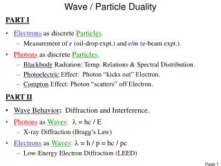
Stanford Wave Induced Particle Precipitation (WIPP) Code. Prajwal Kulkarni U.S. Inan, T.F. Bell March 4, 2008 Space, Telecommunications and Radioscience (STAR) Laboratory Stanford University Stanford, CA. Outline. Motivation Ground-based VLF Transmitters Wave-Particle Interaction

E N D
Stanford Wave Induced Particle Precipitation (WIPP) Code Prajwal Kulkarni U.S. Inan, T.F. Bell March 4, 2008 Space, Telecommunications and Radioscience (STAR) Laboratory Stanford University Stanford, CA
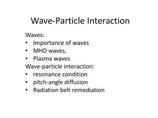
Outline • Motivation • Ground-based VLF Transmitters • Wave-Particle Interaction • Simulation Results • Conclusions
Motivation and Procedure • Resonant interactions with waves are responsible for the acceleration and loss of radiation belt electrons. • In the inner belt and slot region, different types of waves (whistlers, hiss, VLF transmitters) are important drivers of precipitation. • Abel and Thorne [1998a] • Inanet al. [1984] used a test particle approach to calculate precipitation zones around existing ground-based VLF transmitters • Considered only ducted propagation • We calculate the precipitation signatures induced by the NPM, NWC, NLK, NAU and NAA ground-based VLF transmitters as well as by hypothetical transmitters • Utilize the Stanford 2D VLF Raytracing program • Calculate Landau damping along raypath [Bell et al., 2002]. • Calculate energetic electron precipitation based on method of Bortnik et al. [2005a, 2005b]. • We focus on > 100 keV electrons
Transmitter Parameters L = 2.98 f = 24.0 kHz 1000 kW L = 2.75 f = 24.8 kHz 192 kW L = 1.15 f = 21.4 kHz 424 kW L = 1.30 f = 40.75 kHz 100 kW L = 1.38 f = 19.8 kHz 1000 kW
VLF Transmitters 21.4 kHz 424 kW L = 1.15 21.4°
No Magnetospheric Reflections • Wave frequency must be below the local lower hybrid resonance frequency, fLHR • fLHR generally below 13 kHz in inner magnetosphere • Increases at locations closer to the surface of the earth. • Ground based transmitters radiate frequencies above the fLHRand therefore do not MR
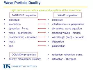
Wave-Particle Interaction H:gyrofrequency : wave frequency kz: wave k-vector : relativistic gamma-factor vz: resonant electron velocity • H effectively determines electron resonant velocity • Higher frequency waves resonate with lower energy electrons • So which factor is most important: location, frequency, radiated power?
Case Study Both at 100 kW, NAA location, equatorial interactions Both at 100 kW Equatorial Interactions Actual locations, 100 kW Off-equatorial interactions Actual characteristics NAA: L = 2.98 (54.6o), 24.00 kHz, 1 MW NAU: L =1.30 (28.6o), 40.75 kHz, 100 kW
Role of Source Location: 100 keV All transmitters at 1 MW radiated power
Role of Source Location: 1 MeV All transmitters at 1 MW radiated power
Conclusion • We have calculated > 100 keV energetic electron precipitation signatures that would be induced by five existing ground-based VLF transmitters • NAA, NLK, NAU, NPM, NWC • NWC induces the strongest precipitation signature • Simulated several hypothetical transmitters distributed broadly in geomagnetic latitude and operating at a wide range of frequencies. • Investigated the relationship between transmitter location, operating frequency and radiated power • H (source location) directly proportional to resonant energy • inversely proportional to resonant energy • Location, location, location! • Future work: compare predictions with data