Download

1 / 26
260 likes | 506 Views
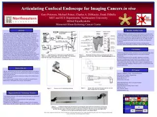
Design of Miniature Manipulators For Integration In A Self Propelling Endoscope. Pratheek Pamidimukkala. Abstract. The endoscope is meant to inspect and intervene in the human colon through which it moves by inch worm motion. The manipulator is used to orient camera and tools. Contd.

E N D
Design of Miniature Manipulators For Integration In A Self Propelling Endoscope Pratheek Pamidimukkala
Abstract • The endoscope is meant to inspect and intervene in the human colon through which it moves by inch worm motion. • The manipulator is used to orient camera and tools
Contd.. • Three different prototypes have been realised • A first design is based on a 3 degree-of –freedom (dof) Stewart platform driven by hydraulic pistons. • A second design is based on a Stewart platform with three telescopic legs, each driven by an electromagnetic motor with spindle.
Contd.. • The third design is a serial arm consisting of two links. Both links are driven by an electromagnetic motor with worm gear reduction • This simple design combines the compactness of the first design with the controllability of the second design.
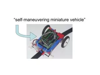
Introduction Fig 1. Self Propelling Robotic Endoscope
Contd.. • The endoscope (fig.1) consists of a propulsion unit, a miniature robotic arm, and a tail. • The propulsion unit consists of two suction clamps connected by an expansion bellow • The tail connects the endoscope to the outer world and contains electrical wiring, pneumatic tubes, tool channel, etc
Hydraulic manipulator design Fig. 2: Hydraulic manipulator design
Contd.. • The design of hydraulic manipulator (fig.2) is based on a 3 degree-of-freedom (dof) Stewart platform. • The platform is driven by three hydraulic pistons which are connected to the upper platform through ball joints which are formed by a steel ball clamped between two PTFE (teflon)discs. • Advantage is its high stiffness and the possibility to have a tool channel running through the center.
Hydraulic Manipulator prototype Fig.3: Hydraulic manipulator prototype in two extreme positions
Contd.. • All parts have been made by a combination of turning, milling, drilling, grinding, wire-EDM (Electro-Discharge Machining), and micro-EDM. • The figure shows the prototype in two of its extreme positions. On the left, the manipulator is in its lowest flat position. On the right, the manipulator is in the fully extended position while maximally rotated.
Hydraulic prototype tests • The kinematics of the hydraulic micromanipulator work well and the construction is rigid and stiff. • Main problem is the friction between rubber o-rings and the stainless steel cylinder block. • The static friction ranges from 0.4 to 0.9 N, depending on piston and cylinder, but also on the time the piston has not moved. The longer the piston is standing still, the higher the static friction.
Valve integration • To keep the tail of the self propelling endoscope as flexible as possible, the number of hydraulic tubes should be as low as possible. • To reduce the number of tubes, valves are under development that can be integrated into the manipulator or endoscopic system. • The idea is to integrate the valves in the actuator block, to enhance miniaturisation and to simplify assembly and hydraulic interconnection.
Electric Stewart platform • The platform has three telescopic legs, each driven by a combination of an electromagnetic micromotor and a microspindle • It consists of two concentric tubes. • In the inner tube, motor, spindle and bearings are mounted. • The outer tube is connected to the spindle nut through a sleeve in the inner tube.
. Fig.4: Electric leg design and prototype
Electric leg prototype • The leg prototype shown in the figure 4 is in its shortest state. • Spindle, inner and outer tube, and the ball joint are made of stainless steel. • Nut, coupling and bearing seats are made from brass. The parts are made by a combination of turning, wire-EDM and micro-EDM. • A linear potentiometer is attached for position measurement
Electric leg characterisation • Due to simplicity of the set-up, the influence of load on speed could only be tested for speeds up to 2 mm/s • At zero load, the maximum speed of the leg is 5 mm/s due to the speed limitation for the motor reduction.
. Fig.5: Serial module design and prototype
Serial manipulator design • It is based on a serial combination of two modules with one rotational dof as shown in figure 5. • A large hole runs through the module to pass the tool channel, camera wiring, illumination fibres, and flushing channel. • The moduleis driven by a miniature gearmotor through a worm gear reduction.
Integration in the endoscope • The manipulator requires two dofs, such that two modules have to be put in series as shown in figure 6. • Advantageous is that camera is integrated into the front module while the other module is for a large part integrated into the frontal clamp. • Therefore, the arm extends only 40mm at the front of the propulsion module.
Both rotation axes are located close to each other such that the manipulator characteristics in both directions are nearly identical. • Rubber bellows seal the manipulator.
Comparison of the manipulators Table.1: Comparision of manipulators
Conclusions • The hydraulic Stewart platform is compact and generates high forces. • The main drawbacks are the high friction, the difficulty to control it, and the relatively stiff tubing. • The electric Stewart platform is much easier to control but is too large.
The serial manipulator has the simplest design and uses a compact worm gear reduction. • Therefore, the serial manipulator combines compactness with the controllability of electromagnetic motors • In case its output torque can be increased, it can be regarded as the best solution.
References • "Design of miniature manipulators for integration in a self-propelling endoscope", J. Peirs, D. Reynaerts, H. Van Brussel, Proc. of Actuator 2000, 7th International Conference on New Actuators, Bremen
Thank You Any questions??