Download
1 / 1
10 likes | 175 Views
System Startup. Initialize memory array for pixel currents with zeros. Initialize all pixel voltages to 0 V . Wait for user action. Change in Pixel Current. Color Button Pressed. Change in Pixel Current. Get ‘Color’ register value. Update ‘Color’ Register. Save Button Pressed.

E N D
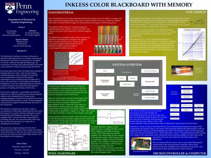
System Startup Initialize memory array for pixel currents with zeros Initialize all pixel voltages to 0 V Wait for user action Change in Pixel Current Color Button Pressed Change in Pixel Current Get ‘Color’ register value Update ‘Color’ Register Save Button Pressed Set pixel current Allocate space in memory for array Update memory Copy pixel array INKLESS COLOR BLACKBOARD WITH MEMORY COIL DESIGN NANOMATERIAL Each display pixel requires its own magnetic field. By passing direct current through loops of magnet wire, one can create an electromagnet to generate such a field only when powered. Using the Law of Biot-Savart, one can determine the field, B, at a particular distance from the loop of wire z, based on its current I, radius r, and number of turns N. This nanomaterial served as the inspiration behind the project. Given its ability to change color when exposed to magnetic fields, it provides an ideal material to use for a multicolor display with color resolution defined largely by the preciseness of magnetic field biasing points. The material itself consists of "superparamagnetic colloidal nanocrystal clusters" of iron oxide that form "ordered structures when exposed to external magnetic fields" The diffraction wavelength (color) of the material can be altered by modulating the strength of the applied magnetic field. A broad spectrum (red to violet) can be created by varying the magnetic field strength from 50 gauss (red) to 500 gauss (violet), while the material when not exposed to any magnetic field is brown in color. Department of Electrical &Systems Engineering Group 4 Furthermore, by use of a ferrite core within the loops of wire, one can scale the field by a constant factor μrod, based on the length-to-diameter ratio and the rod material’s characteristics. The values for B, r, z, and I constrain the design to a particular N but allow for freedom to choose wire diameter d. A longer rod allows for a greater μrodbut increases the thickness of the board. Determining the right d presents a tradeoff between pixel size and increase in resistance per rod (and thus, power dissipation). All of these factors must be considered in design. AdvisorsDr. Jorge SantiagoDr. Dwight Jaggard Lisa FlemingRafi HasibEaswaran Subbaraman Special ThanksPhilip FarnumSid DeliwalaSansern Somboonsong ABSTRACT The blackboard continues to remain a classroom standard, allowing lecturers to visually communicate information and erase it as necessary for reusability. As society continues through the digital age, the convenience of storing notes electronically has become a more attractive means for preserving information. Several products have been developed that attempt to integrate these two ideas, often incorporating a mounted projector with a computer to send and receive information. However, the implicit requirement of an overhead projector makes this a very costly alternative to the traditional blackboard. Furthermore, any extra embedded features offered, in an effort to justify cost, detract from the primary purpose of loading and storing written data. In the chosen approach, a potentially cost-effective alternative is explored, making use of electromagnets within a self-contained device. Based on the superparamagnetic, luminescent properties of an iron oxide based nanomaterial, an array of electromagnetic coils generates magnetic fields that alter the color of the compound. The hardware supporting each pixel is able to accomplish two main goals: detecting when the stylus has passed over a pixel, and then setting the current through the electromagnet to produce the correct magnetic field. A microcontroller, responsible for activating the coils, also stores the state of the array that can then be exported to an image file or redisplayed on the board. The proof-of-concept prototype that has been developed allows the user to draw using one of three colors, and erase as well. The size of the screen is three pixels by five pixels so that single digit numbers and most letters can be displayed. Images of the nanomaterial when exposed increasing magnetic fields SYSTEM OVERVIEW Illustration of the structure of iron oxide colloids that have self assembled when exposed to a magnetic field (1) Prototype coil(3.5” length, 0.125” diameter, 31 AWG wire) Stylus Save & Color Buttons Optical microscope images showing the assembly of CNC’s in a film between two glass slides. The field strength increases from (a to b) (1) Pixel Hardware • All quotes and images taken from: • Ge et al. “Self-Assembly and Field-Responsive Optical Diffractions of Superparamagnetic Colloids”,American Chemical Society, 02/13/2008 Switch Decoder Electromagnet Coil Array Microcontroller Differentiator The hardware, which is identical for each pixel, was designed to simultaneously detect when the stylus passes over its respective pixel as well as to keep the pixel’s electromagnet generating the field needed to maintain color on the board. When the stylus passes over the electromagnet, the induced current in the coil creates a voltage spike at the top of the coil with an amplitude of approximately 30 mV. This node is the input to a differentiator, which produces a voltage output proportional to the change of the input voltage. This voltage spike is amplified to register as a “high” input signal to the microcontroller, as shown in the image on the right. Once the pixel is detected as active, the coil’s color is set. The two bits that the microcontroller outputs are the control bits for a decoder. The decoder ensures that out of the four outputs present (one for each color state), only one is active at a time. Image Formatter Nanomaterial Display Process Flowchart ComputerInterface Computer Display The microcontroller serves as the central processing core for the blackboard, coordinating detection of stylus swipes and the corresponding setting of pixel color, saving the array state to memory, and clearing the board when the user wishes to do so. The microcontroller’s logic for these basic tasks is illustrated in the process flowchart above. Detection of stylus swipes is interrupt-driven, thus minimizing microprocessor usage while maximizing the response time to user input. Each interrupt updates the affected pixel’s color by polling the color buttons and then outputting two bits to the decoder. These two bits represent what color the pixel should be set to – three colors plus “erase”.The pixel hardware then sets the coil voltage to the appropriate value. Finally the microcontroller updates its color value in the array that stores the color values for all of the pixels in the blackboard. Image of voltage spike: differentiator output To obtain different voltages for the different colors, a voltage divider is used. Each voltage is connected an analog switch, all of whose ends are shorted together. The control logic for the switches is the decoder output, which ensures that two different voltages will not be shorted together. This voltage is connected to the base node of a transistor, which isolates the biasing voltages from the electromagnet. The resulting current that flows through the electromagnet produces the correct magnetic field. The save feature allows a user to save a copy of the blackboard’s current state to the microprocessor’s memory. These saved images can then be redisplayed by typing the save position into the computer after specifying that a load is desired. Demo Times Thursday, April 24, 2008 10:30 am – 12 noon 2:00 pm – 3:00 pm Pixel Hardware Circuit Diagram HC11 Microcontroller Board PIXEL HARDWARE MICROCONTROLLER & COMPUTER