Download
1 / 4
40 likes | 168 Views
Ultra-Fast Soft Recovery Diode Module. Description Ultra-FRD module devices are optimized to reduce losses and EMI/RFI in high frequency power conditioning electrical systems. These diode modules are ideally suited for power converters,

E N D
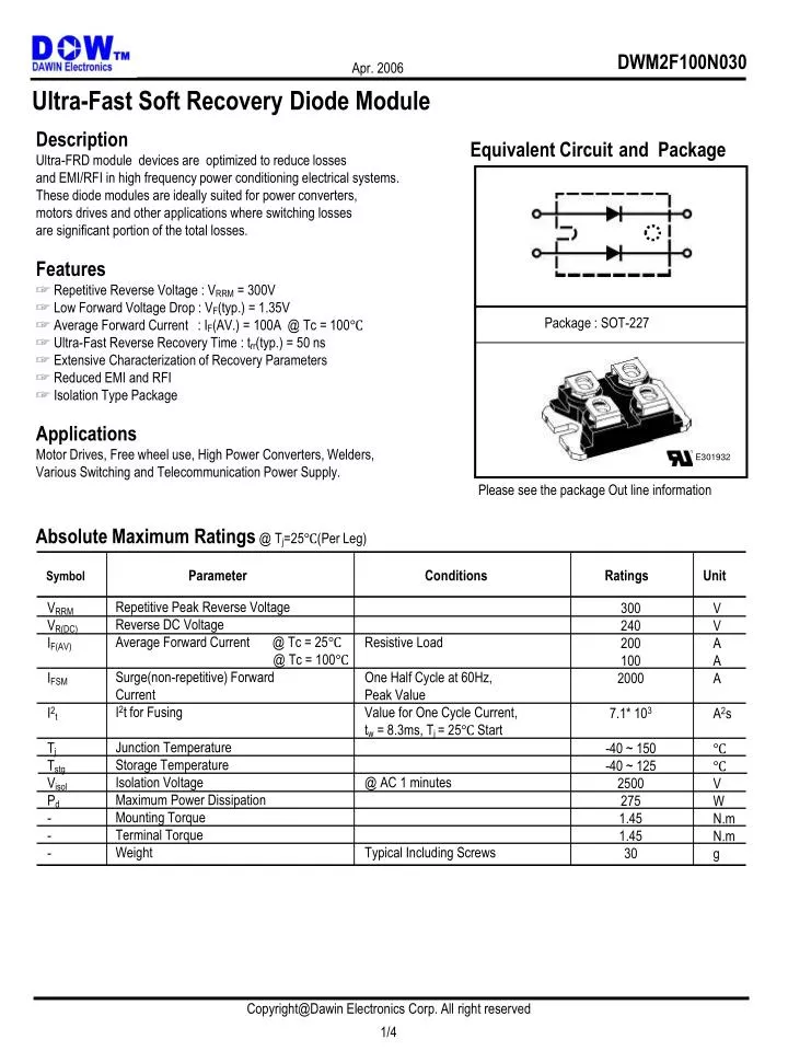
Ultra-Fast Soft Recovery Diode Module Description Ultra-FRD module devices are optimized to reduce losses and EMI/RFI in high frequency power conditioning electrical systems. These diode modules are ideally suited for power converters, motors drives and other applications where switching losses are significant portion of the total losses. Features ☞ Repetitive Reverse Voltage : VRRM = 300V ☞ Low Forward Voltage Drop : VF(typ.) = 1.35V ☞ Average Forward Current : IF(AV.) = 100A @ Tc = 100℃ ☞ Ultra-Fast Reverse Recovery Time : trr(typ.) = 50 ns ☞ Extensive Characterization of Recovery Parameters ☞ Reduced EMI and RFI ☞ Isolation Type Package Applications Motor Drives, Free wheel use, High Power Converters, Welders, Various Switching and Telecommunication Power Supply. Equivalent Circuitand Package Package : SOT-227 E301932 Please see the package Out line information Absolute Maximum Ratings @ Tj=25℃(Per Leg) Parameter Conditions Ratings Unit Symbol Repetitive Peak Reverse Voltage Reverse DC Voltage Average Forward Current @ Tc = 25℃ @ Tc = 100℃ Surge(non-repetitive) Forward Current I2t for Fusing Junction Temperature Storage Temperature Isolation Voltage Maximum Power Dissipation Mounting Torque Terminal Torque Weight VRRM VR(DC) IF(AV) IFSM I2t Tj Tstg Visol Pd - - - Resistive Load One Half Cycle at 60Hz, Peak Value Value for One Cycle Current, tw = 8.3ms, Tj = 25℃ Start @ AC 1 minutes Typical Including Screws 300 240 200 100 2000 7.1* 103 -40 ~ 150 -40 ~ 125 2500 275 1.45 1.45 30 V V A A A A2s ℃ ℃ V W N.m N.m g 1/4
Thermal Characteristics Values Parameter Conditions Unit Symbol Max. Typ. Min. Rth(j-c) Thermal Resistance Junction to Case 0.45 ℃/W - - Electrical Characteristics @ Tj=25℃ (unless otherwise specified) Values Unit Parameter Conditions Symbol Max. Typ. Min. Cathode Anode Breakdown Voltage Maximum Forward Voltage Repetitive Peak Reverse Current Reverse Recovery Time V V V mA ns ns VR VFM IRRM Trr IR = 100uA IFM = 100A, Tc = 25℃ IFM = 100A, Tc =100℃ TC = 100℃, VRRM applied IFM = 100A, VR = 200V di/dt=-100A/us 300 - - - - - - 1.35 1.1 - 50 80 - 1.6 1.4 1.0 75 - Tc = 25℃ Tc = 100℃ 2/4
Average Forward Current IF(AVG) [A] DC Case Temperature Tc[℃] Fig. 4 : Forward Current Derating Curve Performance Curves Fig. 1 : Typical Forward Voltage Drop vs. Instantaneous Forward Current Fig. 2 : Typical Reverse Recovery Time vs. -di/dt Fig. 3 : Transient Thermal Impedance(Zthjc) Characteristics 3/4
Package Out Line Information Dimensions in mm SOT-227 4/4