Download
1 / 73
1.38k likes | 3.12k Views
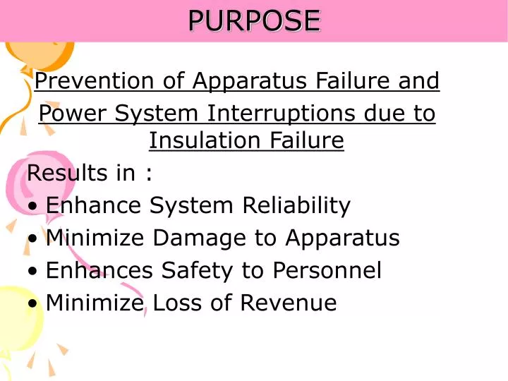
PURPOSE. Prevention of Apparatus Failure and Power System Interruptions due to Insulation Failure Results in : Enhance System Reliability Minimize Damage to Apparatus Enhances Safety to Personnel Minimize Loss of Revenue. Benefit. Extension of Apparatus Life

E N D
PURPOSE Prevention of Apparatus Failure and Power System Interruptions due to Insulation Failure Results in : • Enhance System Reliability • Minimize Damage to Apparatus • Enhances Safety to Personnel • Minimize Loss of Revenue
Benefit • Extension of Apparatus Life • Degradation of Insulation, if detected before failure, can generally be restored to its original condition • Defer replacement costs • Better Utilization of Resources • Inspection interval may be safely extended or scheduled to utilize resources efficiently and effectively • Verification of new apparatus • Verify that new apparatus meets purchased specification and agrees with factory test reports • Assures proper field Assembly
Definition • What is a Power Factor/ Dissipation Factor / Tangent Delta Test?… • The underlying principle of this test is to measure the fundamental AC electrical characteristics of insulation.
Clarification • Insulation vs. Dielectric • Insulation relates to a medium’s ability to prevent the flow of current, I.e. poor conductivity. • Dielectric implies that the medium or material has specific measurable properties such as: Dielectric Strength, Dielectric Constant, Dielectric Loss and Power Factor.
Dielectric Constant • In 1836, Michael Faraday (the father of the Capacitance) discovered that when the plates between a capacitor were filled with another insulating material, the capacitance would change. • This factor is the dielectric constant e • By definition the dielectric constant of a Vacuum is 1.0. Oil e=2.2 Vacuum Cvacuum=10 pF Coil = ex Vacuum = 22 pF
Dielectric: An Atomic View - - - - + + + + - - + + - - - - + + + + A Dielectric at Rest with no applied voltage. The molecules have no polar orientation. molecules The molecules acquire a dipole moment resulting in a Negative charge building up on the Positive plate and a positive at the negative plate. This polarization creates an opposing electric field resulting in a diminished applied voltage. + E -
Perfect Insulator • The Capacitor
Ideal Insulation System • Evaluating Insulation System
Resistive Component • The Resistor IR = IT IR = E/R W=EIR q=0o E IR
Basic Insulation Circuit • Basic Power/Dissipation Factor Circuit
Definition • The Term Power/Dissipation Factor Describes • The phase angle relationship between the applied voltage across and the total current through a specimen. • The ratio of the real power to the apparent power. • The relationship between the total and resistive current
Basic Insulation & Power Factor Theory IC IT d Q IR E • Power Factor Vs. Dissipation Factor Vs. Tangent Delta
Insulation System C1 C2 C3 Insulation Systems can be modeled as a Series of dielectrics... C1 C2 C3 C4 Or as parallel dielectrics... or a combination of the two.
DC Testing on Series Insulation BAD DC Test Voltage Short Stop BAD DC Test Voltage Test Results: Good Insulation System: Bad Stop • If the first dielectric is good. The DC Test will indicate good; any • remaining dielectrics will not be tested. Test Results: Good Insulation System: Bad • For a DC test to be good, only one dielectric needs to be in good condition During an AC Test the power factor will change as each dielectric fails.
DC Testing on Series Insulation Cont. DC Test Voltage Short Short Test Results: Bad Insulation System: Bad For a DC Test to indicate an unsatisfactory result, all dielectrics must be in poor condition.
DC Testing on Parallel Insulation DC Test Voltage • If one dielectric fails in a parallel dielectric, the test will fail. • There is no way to tell if the other dielectrics are good or bad. During an AC Test the power factor will change as each dielectric fails.
Advantage of AC vs. DC Tests • The AC test has a common factor in the form of a ratio (% Power Factor), which is independent of the amount of insulation. • The AC test is not hindered by a layer of “good” insulation in series with a “bad” insulation, since it merely requires a capacitance coupling. • The AC test provides a direct measure of dielectric loss and capacitance, both of which are useful in the diagnosis of the deterioration of many forms of insulation. • The DC test measurement depends on the length of time the voltage is applied. (PI)
Limitation of the AC Dielectric-Loss • The ability to detect localized defects decreases as the inherently normal dielectric-loss and capacitance of the insulation systems increases. • Defects which are voltage dependent may not be detected if the initiation voltage of the defect is greater than the test voltage.
Voltage sensitive characteristics • When we closely examine insulation, very small gaps or “voids” could exist. These voids develop an electrostatic potential on their surfaces. These small gaps become ionized: Partial Discharge/Corona. Voids
Results Interpretation Increase in Tan Delta indicates: • Chemical deterioration due to ageing and temperature or local overheating • Contamination of water, carbon deposits, bad oil, dirt etc. • Severe leakage through cracks and surfaces • ionization
FACTORS AFFECTING TAN DELTA • TEMPERATURE • HUMIDITY • SURFACE LEAKAGE • ELECTROSTATIC INTERFERENCE • SYSTEM FREQUENCY
FACTORS AFFECTING TAN DELTATEMPERATURE • AT LOW TEMP. DUE TO HIGH VISCOSITY, MOTIONAL RESPONSE OF IONS AND POLAR COMPOUNDS SMALL AND HENCE LOW DIELECTRIC LOSS. • AS TEMPERATURE INCREASES, THE VISCOSITY DECREASES AND HENCE AMPLITUDE OF MOTION INCREASES TO INCREASE THE DILECTRIC FRICTIONAL LOSSES.
FACTORS AFFECTING TAN DELTAHUMIDITY AND SURFACE LEAKAGES • IN HUMID ATMOSPHERE TEST OBJECT ACQUIRE DEPOSIT OF SURFACE MOISTURE WHICH RESULTS IN SURFACE LEAKAGE ERRORS • DIRT ON SURFACE OF TEST OBJECT INCREASES LEAKAGE CURRENT
FACTORS AFFECTING TAN DELTAELECTROSTATIC INTERFERENCE • IN ENERGISED SUBSTATIONS CAPACITIVE COUPLING BETWEEN SPECIMEN AND CHARGED SYSTEM IS FORMED • INTERFERENCE SUPPRESSORS ARE USED IN TESTING KITS • MEASUREMENT IN NORMAL & REVERSE POLARITY APPLIED
MODES OF MEASUREMENT • UST • GST • GSTg
UST • USED WHEN TESTING IS DONE ON UNGROUNDED (ISOLATED FROM EARTH) OBJECT LIKE BUSHINGS, CTs WITH TEST TAP, CVTS AND GRADING CAPACITORS OF CBs
GST • USED WHEN OBJECT IS GROUNDED AND WHEN TWO SPECIFIC POINTS (ISOLATED FROM GROUND) ARE NOT AVAILABLE FOR TAN DELTA MEASUREMENT. EXAMPLE: TRANSFORMER / REACTOR WINDING , CTs WITHOUT TEST TAP
GSTg • USED TO SEPARATE THE TOTAL VALUES OF GST TEST FOR BETTER ANALYSIS • FOR EXAMPLE IN TRANSFORMER HV-IV /LV+G-------GST------CHL + CHG HV-IV / LV WITH Guard-----GSTg---CHG
C – TAN DELTA MEASUREMENT • TRANSFORMER (BUSHING & WINDING) • REACTOR (BUSHING & WINDING) • CVT • CT • CB (GRADING CAPACITOR) • LA (NEWLY INTRODUCED)
TEST FREQUENCY • Bushing----2Y • Winding----4Y • Grading Capacitor----4Y • Current Transformer---Y • CVT---4Y
Transformer Types • Power and distribution transformers may be either single-phase or three-phase • Three-Winding • Two-Winding • Autotransformer (with or without a tertiary winding) • They may be liquid-insulated, gas-insulated, or dry-type. For test purposes, the procedure used depends on the number of accessible, separatewindings.
Transformer Insulation Systems High Voltage Windings CHG CHL CLG Low Voltage Windings For simplicity, transformer insulation is grouped into three representative insulation systems CHG CLG CHL
WINDING COMBINATION FOR C & TAN DELTA MEASUREMENT IN AUTO TRANSFORMERS
Dielectric Circuit: Two Winding Transformer CH - Insulation between High-Voltage conductors and grounded Tank & Core (H Bushings-Winding Insulation-Structural Insulating Members-Oil) CL - Insulation between Low-Voltage conductors and grounded Tank & Core (X Bushings - Winding Insulation-Structural Insulating Members-Oil) CHL - Insulation between High- and Low-Voltage Windings (Winding Insulation-Barriers-Oil) High CH Tank and Core CHL CL Low
Physical Representation of Three-Phase Two-Winding Transformer High-Voltage Windings Low-Voltage Windings One of Three Phases Shown CH CHL CL Core Leg Transformer Tank
The Overall Test CH CHL CL • Before you start the overall test: • Short Circuit High Voltage Windings • Short Circuit Low Voltage Windings • Disconnect the neutral bushing from • ground This is one of the most common sources of error in test results! Ensure that the Neutral Bushing is also shorted and disconnected from Ground
Hookups for the Overall Tests High CH GST-Ground Test #1 : CH+CHL CHL CL Low High GST-Guard CH Test #2: CH CHL CL Low High CH UST Test #3: CHL CHL CL Low
Dielectric Circuit for Three-Winding Transformers High Tank and Core CH CHL Low CHT CL CLT Tert CT
Bushing Types • Condenser type: • Oil-Impregnated paper insulation • Resin bounded paper insulation • Non-condenser type: • Solid • Alternate layers of solid and liquid insulation • Gas-filled
Bushing Tests • Main insulation - C1 • Center Conductor to Tapped Layer • Tap insulation - C2 • Tapped Layer to Ground Flange • Overall insulation • Center Conductor to Flange, only applicable when not installed on an apparatus • Hot Collar Test
Center Conductor Sight-Glass Liquid or Compound Filler Insulating Weather shed Main Insulating Core Tap Insulation Tap Electrode Mounting Flange Ground Sleeve Tapped Capacitance-Graded Layer Lower Insulator Components of a Typical Oil-Impregnated Capacitance-Graded Bushing
Liquid/Compound Filler Tapped Capacitance-Graded Core Layer Main insulating Core Insulating Weather shed Capacitance Graded Core Layers Tap Cover Filler Plug Connection to Tapped Core Layer Tap Electrode Tap Insulation Mounting Flange Permanently Grounded Core Layer Ground Sleeve Typical Bushing Potential Tap Construction
Condenser Bushing Construction Main Insulation C1 Grounded Layer/Flange Center Conductor CK CA = CB = CC = CD = CE = CF= CG = CH = CI = CJ V1 = V2 = V3 = V4 = V5 = V6 = V7 = V8 = V9= V10 Tap Electrode Line-to-Ground System Voltage The Condenser Bushing allows an Energized Conductor to Penetrate a Ground Plane. Voltage is stressed equally across each layer of the condenser bushing
High-Voltage Cable • Test Includes • Main C1 Core Insulation Main-Insulation/C1 Test Standard Method Test Mode: UST LVL Test Set Ground Lead Bushing and Apparatus Ground
C1 Center Conductor C2 Dielectric Circuit: Main-Insulation/C1 Test High Voltage Lead Low-Voltage Lead Test Tap C1 Guard Test Ground Current & Loss Meter Test-Set Ground Lead
Test Includes • Tap Insulator • Core Insulation between tapped Layer and Bushing Ground Sleeve • Portion of Liquid or Compound Filler • Portion of Weathershed near Flange LVL Test Mode: GST-Guard HVL Tap-Insulation/C2 Test Standard Method C2 Guard
C1 Center Conductor C2 LVL HVL Tap-Insulation/C2 Test Standard Method C2 Guard Test Ground Test Mode: GST-Guard
High-Voltage Cable • Test Includes • Main C1 Core Insulation • Insulating Weathershed • Sight-Glass • Lower Insulator • Portion of Liquid or Compound Filler Test Mode: GST-Ground Guard Test Set Ground Lead Overall Test Bushing and Apparatus Ground
LVL Single Hot Collar Test UST Mode Test Set Ground Lead Test Mode: UST Guard • Test Includes • Portion of Insulating Weathershed • Sight-Glass • Core Insulation in Upper Area • Liquid or Compound Filler in the Upper Area Bushing and Apparatus Ground