Download

1 / 34
340 likes | 504 Views
Outdoor Image Processing. Photometric stereo for outdoor webcams. "Photometric stereo for outdoor webcams" Ackermann , J.; Langguth , F.; Fuhrmann , S.; Goesele , M.; , CVPR 2012 Overview: Photometric stereo from time lapse video captured over a long time span . Retrieves

E N D
Photometric stereo for outdoor webcams • "Photometric stereo for outdoor webcams" Ackermann, J.; Langguth, F.; Fuhrmann, S.; Goesele, M.; , CVPR 2012 Overview: • Photometric stereo from time lapse video captured over a long time span. • Retrieves • Surface Normals • Basic Materials • Material Mixtures • Indirect light
Assumptions • GPS location of the camera, object and sky mask, per image time stamp are available
Selecting Subsets of images • Image Filtering: 1) Discard images with 10% of the image or the object is overexposed 2) Select only daytime images, zenith < 85 degrees 3) Discard bad weather images – select only top 50% according to score: SI= Isky + IObj Isky = median of sky pixel intensities IObj = 75th percentile of object pixel intensities
Selecting Subsets of images • Two Image subsets required; 1) Clear sky images for camera calibration, 2) Images with good weathers and well illuminated object for photometric stereo Iteratively select required number of images by updating penalty using a 2D Gaussian function and selecting the best image at that iteration
Obtaining light direction • Image Alignment: Align gradient images to the average gradient • Camera Calibration: 1) Radiometric response obtained using Kim et al. ( uses pixels under the same lighting conditions to solve for the response function). 2) Absolute zenith, azimuth of the Sun obtained using cam location, timestamp. 3) Use the sky as calibration target ( Lalonde et al.) to find camera zenith, azimuth • Shadow Detection • Imax,p/ Imin,p < 1.4 => always shadowed • Otherwise, Ii,p < 1.5*median10% darkest pixels => shadowed in Ii End of Stage 1 ( obtain subset of images with light direction)
Photometric Stereo stage • Intensity of image i at pixel p and channel c, Ii,p,c = Isun,i,p,c + Isky,I,p,c • Reflectance at a pixel is linear combination of basis materials, fm,c Sun light model Portion of sky visible at p Surface normal Intensity of the sun Sun direction Material mixing coeff
Light Model • Sky light model Assume Finally, Optimize for li,c, fm,c, np, γp,m. Vp is replaced by using images Ips.t. pixel p is not in shadow
Initialization • Set Sp,cto zero , assume constant light intensities and Lambertian scene • Obtain initial estimates for surface normals and albedo • Use these to find initial estimates of the light intensities • Cluster the albedos to get an initialization of material properties at each pixel 1) Surface normal and albedo • Solve for classical photometric stereo
Initialization • 2) Relative light intensities: • Need six surface points with similar albedo and differing normal • 1) Cluster albedos in 4 groups • 2) Cluster normals for pixels with the most frequent albedo • 3) Pick normal from different clusters • 3) Initial material estimation: • Cluster albedos in sRGB • Identify pure pixel sets for each of the fundamental materials • Solve for the BRDF parameters
Iterative Refinement • Intensity estimate: updated in each following step 1) Material Fitting • Find optimal parameters for all materials simultaneously, not for only pure pixels • Minimize
Iterative Refinement • Light intensity optimization: • Minimize , • Material and normal map optimization: • Minimize • Material parameters, light intensities are fixed, only normals, sky light at each pixel, and material mixing coeff are optimized
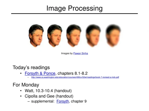
Shadow Detection and Removal • Single-Image Shadow Detection and Removal using Paired Regions RuiqiGuo, QieyunDai, Derek Hoiem. CVPR 2012 • Employs a region based approach. • Perform pairwise classification (of illumination conditions) of regions based on appearance. • Graph cut is used for the labeling. • Soft matting for refinement • Shadow free image is obtained by relighting pixels under shadow
Shadow Detection • Maximize • cishadow– single region classifier confidence * region area • cijdiff, cijdiff– pairwise classifier confidence * f(region areas) • y – shadow labels for regions
Shadow Detection • Single region classifier (with χ2 kernel) features • Color histograms • Texton histograms • Internal appearance of a given region is not enough Comparison between regions of same material needed Pairwise region classifier (RBF kernel) features • Χ2 distance between color and texton histograms • Ratios of RGB average intensity ( ρr = Ravg1 /Ravg2, …) • Chromatic alignment (ρr/ρg) • Normalized distances between the regions
Pairwise region graph • Different illumination • black-white • Same-illumination • Green • Not related • Orange
Apply Graph cut • Reformulate the cost function to apply Graph cut
Shadow Removal Hard shadow mask Soft shadow matt Soft shadow Solution: Shadow matting Slide from Guo et al.
Shadow Removal Direct light • Simple light model: direct light + env. Light • Relighting: Estimate how much direct light is occluded at each pixel and light up by that amount • Find the fractional shadow coefficients using matting technique • Find ratio of direct to environment light. Surface Reflectance Environmental light Shadow coefficient content from from Guo et al.
Light Model Non-shadow: ti=1 Umbra: ti=0 Penumbra = 0 < ti < 1 Relighting : Iishadow-free = (Ldcosθi + Le)Ri Figure from from Guo et al.
Shadow model as a matting problem Ii = γiFi + (1-γi)Bi F: Foreground image, B: background Image Rewrite shadow model as: Ii = ki(LdRi + LeRi) + (1-ki)LeRi Similar to matting eqn. Solve for matting: minimize E(k) = kTLk + λ(k-k’)TD(k-k’)T optimal k obtained by solving sparse system: (L+ λD)k = λdk’
Finding the light ratio Final r obtained by voting content from from Guo et al.
Results • UCF Dataset (Zhu et al.) • 245 images • outdoor scenes, manual annotations content from from Guo et al.
Experiments: Datasets • UCF Dataset (Zhu et al.) • 245 images • outdoor scenes, manual annotations content from from Guo et al.
Experiments: Datasets • New UIUC Shadow Dataset • 108 images, indoor/outdoor, automatic annotation • Evaluate both shadow detection and removal Groundtruth Nonshadow Shadow mask Input image content from from Guo et al.
Results on UCF Dataset Groundtruth Shadow mask Detection Removal result Input image content from from Guo et al.
Results on UIUC Dataset Detection Removal result Groundtruth Input image content from from Guo et al.
Results: Shadow Detection Pixel accuracy content from from Guo et al.
Results: Shadow Detection Confusion matrices on UCF dataset full model Single region classification content from from Guo et al.
Results: Shadow Detection Confusion matrices on UCF dataset full model Zhu et al. 2010 content from from Guo et al.
Failure Example Input image Detection Removal result content from from Guo et al.