Download
1 / 20
200 likes | 313 Views
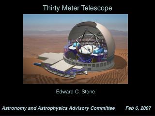
Seismic Design Considerations for the Thirty-Meter Telescope. Mike Gedig, Dominic Tsang, Christie Lagally Dynamic Structures Ltd. Dec 3, 2007. Outline. Overview of TMT configuration Seismic performance requirements Load determination Tools and methodologies Preliminary results

E N D
Seismic Design Considerations for the Thirty-Meter Telescope Mike Gedig, Dominic Tsang, Christie Lagally Dynamic Structures Ltd. Dec 3, 2007
Outline • Overview of TMT configuration • Seismic performance requirements • Load determination • Tools and methodologies • Preliminary results • Restraint design • Criteria and considerations
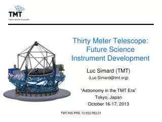
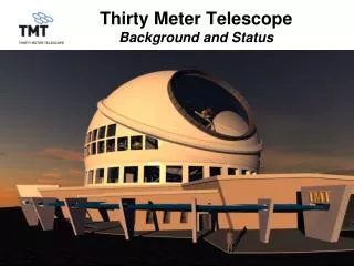
Overview of TMT configuration • TMT is a new generation of Extremely Large Telescope with a segmented primary mirror diameter of 30m • Overall system mass is estimated to be 1700T • Including steel structural mass of 1050T • System is supported on bearings which allow rotations about 2 axes and restrain lateral motions during operation • Fundamental frequency ~ 2.2 Hz (including soil and foundation)
Model Refinement - Overview • Finite Element Model M1 Cell Elevation journal M2 Elevation bearings (4) Elevation structure M3 Nasmyth deck Instrument support structure Azimuth structure Azimuth track Azimuth bearings (6) Foundation and soil springs Pintle bearing (Lateral hydrostatic shoe bearing)
Seismic performance requirements • Two performance levels • Operational Basis Survival Condition (OBS): After a 200-year average return period earthquake (EQ) event, structure shall be able to resume astronomical observations and regular maintenance operations with inspection lasting no longer than 6 hours • Structure is expected to behave elastically • Maximum Likely Earthquake Condition (MLE): After a 500-year average return period EQ event, structure shall be able to resume astronomical observations and regular maintenance operations within 7 days • Minor damage at seismic load resisting elements are tolerated; the rest of the system remains elastic • Telescope Structure System is required to sustain multiple OBS events without damage, and multiple MLE events with damaged seismic load resisting elements.
Load determination • Site-specific seismic hazard analysis • Seismic hazard analysis: uses information on local seismology and geology, such as the location of surrounding faults, to calculate earthquake event probability • Spectral matching: generates time histories that match a given design spectrum from input time histories; input should correspond to site with similar seismicity and geology, and matching should consider earthquake magnitude, distance and duration • Site response analysis: generates a time history at surface using an input time history at bedrock level and a layered soil model • Commercial software EZ-FRISK will be used • Reference to technical codes • American Society of Civil Engineers “Minimum Design Loads for Buildings and Other Structures (ASCE7) • International Building Code (IBC) • Local building code
Load determination • FEA: perform both response spectrum and time-history analyses • Spectrum analysis is more straightforward but is restricted to linear elements • Time-history analysis can provide more realistic results but is computationally demanding • Solution: Create a simplified FE model representative of the full FEM • The complete telescope structure contains about 18,000 nodes and 35,000 elements • Apply substructuring techniques to reduce the number of DOF down to ~100 and cut computation time significantly • Stiffness distribution of original model is maintained • Mass distribution in the simplified model needs to be calibrated against the that of the full model • Sensitivity analyses will be conducted to examine the effect of uncertainties in some parameters (e.g. bearing stiffness, damping, soil properties, etc)
Load determination • Other highlights of time-history analysis • Soil / foundation is included in the FEM to evaluate ground effects • Rayleigh damping model will be used to define damping for time-history analyses • Involves mass- and stiffness-matrix multipliers (alpha & beta), which governs the damping ratio vs. modal frequency • Damping is a large uncertainty in seismic design, further discussion at the end of presentation if time permits • Seismic restraint can be modeled with non-linear elements • Subsystem loads • There may be further load amplification for delicate components, e.g. M2, M3, and Nasmyth instruments, which are modeled as lumped masses in the FEM • Local response spectra will be generated to examine this effect in terms of support structure stiffness
Preliminary results • Analysis Assumptions • Based on 500-yr return-period spectral and time-history data from Dames & Moore’s “Seismic Hazard Analysis” report for Gemini • Seismic loads are applied to ground nodes in x-direction • Spectrum analysis • Based on D&M response spectra • Use 2% constant damping ratio • Transient analysis • Based on D&M “Modified Mauna Loa” time history @ 30 deg. • Set 2% damping for frequency range of 2 to 10 Hz by applying appropriate alpha & beta damping values
Preliminary results • Three sets of results • #1: Spectrum analysis, all-linear system including seismic restraint • #2: Transient analysis, all-linear system including seismic restraint • #3: Transient analysis, all-linear structure with non-linear seismic restraint • For this third set of results, restraint is modeled as a bilinear spring with a force limit of 2000 kN, i.e. behaves plastically if force limit is exceeded at a given time * For comparison, base shear ~ 13300 kN using ASCE 7’s equivalent lateral force procedure
Preliminary results • Time-history results • Below shows acceleration amplification from ground to top-end
Preliminary results • Time-history results • Below shows displacement amplification from ground to top-end
Seismic restraint design • Restraint design criteria and strategies • The restraints must not interfere with normal telescope operations • The restraints are the primary lateral-motion resisting devices during a survival-level earthquake and protect the rest of the structure from damages • Lateral load-resisting ability of lateral hydrostatic shoe bearing may be utilized to a limited degree • The structure and restraints should both behave elastically during an operational-level earthquake • The restraints may behave inelastically during a survival-level earthquake to keep the structural loads within the elastic level • The restraints should retain sufficient stiffness and strength to also protect the structure against aftershocks • Telescope downtime in order to “reset” the seismic restraint must be compatible with the observatory requirements with operational considerations included in the design for repair and replacement, structural re-alignment, and equipment re-calibration, etc.
Seismic restraint design • Design considerations • Two fundamental restraint design choices: • Serial or parallel (or combination) load path with lateral hydrostatic bearing (HSB) • Linear or Non-linear restraint • Type of non-linearity: friction, yielded component, buckling-restrained braces • Factors that drive the restraint scheme choices: • Amount of forces transmitted to structure • Required load capacity of the lateral HSB • Analysis complexity • Analysis accuracy • Fabrication tolerance requirements • Installation tolerance requirements • Relative cost • Downtime • The goal is to protect the telescope structure with the simplest and most economical restraint design
Seismic restraint design • Linear vs. non-linear restraints
Seismic restraint design • Restraints with serial vs. parallel load path with lateral HSB
Damping • Damping is a major source of uncertainty in seismic design • Damping occurs through different mechanisms • Structural damping (complex-stiffness damping) • proportional to vibration amplitude • different damping levels for different design earthquakes • range of 0.5% to 2% will be considered for TMT as conservative values
Damping • Recommended design values for general steel structures • wide range of values • Survey of structural damping coefficients in telescope design *recommended for low amplitude vibration
Damping • Measured damping coefficients • damping can be calculated by instrumenting a structure with accelerometers • structure can be excited by instrumented hammer or by existing loads such as wind • damping values are typically low because vibration amplitude is low, and are too conservative for design • Statistical analysis of damping coefficients • Bourgault & Miller evaluated damping coefficients for 22 space-based structures • For frequency range 0.14-9.99Hz, damping coefficient has mean 1.9% and standard deviation 1.58% • Gamma probability density function for space-based structures may be used for other structures, such as buildings


![[79.03] The Thirty Meter Telescope (TMT) Project](https://cdn1.slideserve.com/1737456/79-03-the-thirty-meter-telescope-tmt-project-dt.jpg)