Download
1 / 29
300 likes | 677 Views
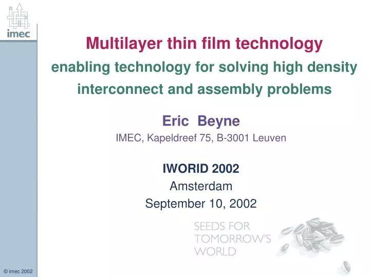
Multilayer thin film technology enabling technology for solving high density interconnect and assembly problems. Eric B eyne IMEC, Kapeldreef 75, B-3001 Leuven IWORID 2002 Amsterdam September 10, 2002. Outline. Introduction :

E N D
Multilayer thin film technologyenabling technology for solving high density interconnect and assembly problems Eric Beyne IMEC, Kapeldreef 75, B-3001 Leuven IWORID 2002 Amsterdam September 10, 2002
Outline • Introduction : Impact scaling trends microelectronic circuit technology on packaging & interconnection technology • Interconnect technology gap • Multilayer thin film technology • Application examples • Conclusion E.Beyne
500 350 95 97 99 01 03 05 07 10 250 180 130 100 (DRAM Half-Pitch) Minimum Feature Size (nm) 1998 / 1999 ITRS 70 50 ISMT Litho 2001 Plan (2-year cycle to 50nm) 35 2000/2001 ITRS 25 95 97 99 01 03 05 07 10 Trends in IC process technology • Continuous miniaturization E.Beyne
System-on-a-chip, SOC • SIA Roadmaps : continuation of Moore’s Law • Decreasing transistor size : smaller die for same function • For the same functionality : higher I/O density • Faster transistor operation • Increasing system complexity • Up to today : faster growth than size reduction • larger die sizes • Feasibility of “System-on-a-Chip” SOC architectures E.Beyne
System-in-a-package, SIP • Single Chip SOC systems ? • There is a divergence among Si-technologies : high density logic (CMOS), Memory, Analog, rf, MEMS,…. • Systems consist of many non-silicon components : Passives, Displays, sensors, antennas, connectors, … • SOC single component system • “System-in-a-Package” SIP solution : • = Multiple components on a high density interconnect substrate, realizing a (sub)-system function • Contradiction SOC - SIP ? Because of SOC, (sub)systems may be miniaturised to the scale of a package E.Beyne
Miniaturisation of Electronic Systems • Enabling Technologies : • Si-integration : SOC • High Density Interconnection technologies • SIP – “System-in-a-package” E.Beyne
Chip/board area ratio very low Limited by the Printed circuit board technology Interconnection technology • Example : Direct chip attach of bare die on printed circuit board Motorola E.Beyne
PCB scaling Advanced PCB Size scaling Laser via Interconnect Gap IC scaling Time The Interconnection gap • Improvement in density of standard interconnection and packaging technologies is much slower than the IC trends E.Beyne
The Interconnection gap • Requires new high density Interconnect technologies PCB scaling Advanced PCB Size scaling Thin film lithography based Interconnect technology IC scaling Reduced Gap Time E.Beyne
300 Via hole Ø SBU board Via pad Ø SBU board 250 m) Via hole Ø thin film m 200 Via pad Ø thin film 150 Via Diameter ( 100 50 0 0 20 40 60 80 IC Technology m Line Width/Spacing ( m) The interconnect gap Scaling Most advanced PCB technologies (SBU) E.Beyne
PCB dimensions Not compatible with Ultra fine-pitch flip chip or wire bonding Connecting high density IC’s • IC • Peripheral • Bond pitch : • 100 40 mm • High speed PCB Direct attachment Wire bond or flip chip • Laminate technology • Line width & Spacing : • 100 50 mm E.Beyne
Chip sized package • Area array redistribution • (multilayer thin film) • “above” IC processing • Solder ball connections, 300 m Ø • Solder ball pitch : 800 300 mm Connecting high density IC’s • IC • Peripheral • Bond pitch : • 100 40 mm • High speed PCB • Laminate technology • Max.contact pitch : • 800500 mm Only for large area die (low I/O density) Such as memory E.Beyne
“Interposer” Connecting high density IC’s • IC • Peripheral • Bond pitch : • 100 40 mm • High speed PCB • Laminate technology • Max.contact pitch : • 800500 mm E.Beyne
Function IC package : “Geometry transformer” • The fine I/O pitch has to be connected to the coarser interconnect pitches on board level IC Package – “Interposer” Interconnect Board E.Beyne
Wire bonding • “Interposer” • High density • substrate • Down to 40 mm pitch Flip Chip • Peripheral • Down to 40 mm pitch • Area array redistribution • Below 250 mm pitch Connecting high density IC’s • IC • Peripheral • Bond pitch : • 100 40 mm • High speed PCB • Laminate technology • Max.contact pitch : • 800500 mm E.Beyne
Multiple IC Wire bonding • Down to 40 mm pitch Multilayer thin film Technology with embedded passives Flip Chip • Peripheral • Down to 40 mm pitch • Area array redistribution • Below 250 mm pitch Passives Connecting high density IC’s • IC • Peripheral • Bond pitch : • 100 40 mm • High speed • “Interposer” • High density • substrate “System-In- a-Package” SIP PCB • Laminate technology • Max.contact pitch : • 800500 mm E.Beyne
Photoresist patterning(shape!) Metal deposition (evaporation) Lift-off resist : gap pattern Deposition lift-off photoresist Resist deposition & photo patterning Wet etch (isotropic) Resist strip : gap >> pattern Deposition withuniform thickness Resist deposition & photo patterning on metal seed layer Seed layer back-etch : Gap pattern Resist strip Electrodeposition (Thick) Metal Thin film metal interconnect patterning Lift-off metal patterning Subtractive etching Semi-Additive electroplating E.Beyne
Disadvantages : limited thickness of metal layers precision limited by wet etching min. space/width : 15mm / 10mm High capital cost of equipment and materials Disadvantages : difficult thickness control relatively rough surfaces many processing steps involved only limited number of metals available (Cu, Ni, Au, Ag, Co,…) Thin film metal interconnect patterning • Subtractive technique : e.g. Ti/Cu/Ti layers • Advantages : • smooth metal surface • excellent thickness control • low number of process steps • Mulilayer metal stacks easy • Semi-additive : e.g. Ti/Cu seed layer + Cu plating • Advantages : • thick metal layers possible • definition by photoresist : • lines up to 10 mm thick, • min. line width / spacing : • down to 5mm/5mm • Lower cost process E.Beyne
Key features multilayer thin film technology • Metal interconnect lines • Dimensions : • Width/Spacing : 20/10 mm down to 5/5 mm • Thickness : 1 mm up to 5 mm • Copper : additive electroplating • Metal finish : Ni/Au plating • Dielectrictric layers • Spin-on polymers – e.g. BCB • Thickness per layer : 5/10 mm • Via hole diameter : 20 – 40 mm • Integrated passives • Thin film resistors (TaN, NiCr,…) • Thin film capacitors (Ta2O5, SiN4,…) • Inductors : Cu E.Beyne
Dielectric (BCB) Si wafer Cu/low K interconnect Electroplated Cu Cu bond pad Electroplated Ni(UBM) Chip passivation Electroplated Au Preform solder ball Wafer Level Pad Redistributionfor flip chip and wafer level CSP Wafer level CSP Solder balls >300 mm Flip chip redistribution Solder balls <100 mm E.Beyne
Thin film Interposer technology • Thin film Redistribution process • on on laminate substrate 60 mm flip chip bump pitch E.Beyne
High Density Thin Film Interconnects for Digital Applications • Technology : • Substrates : 150 mm Ø, Si, glass, ceramic, high Tg laminate or metal. • BCB spin-on photosensitive dielectric layers • Cu lines, 3-5m thick, down to 10m wide lines & spaces • Metal finish top surface : Cu/Ni/Au • Power & ground layers : 2 m thick Al • Integrated decoupling capacitors (0.75 nF/mm2) • Design : • “Manhattan” style X-Y routing, • Automated design methodology E.Beyne
Current Electronic systems • High component count & Large variety of technologies • Majority of components : passives • Many non-silicon components : displays, key-pad, connectors … Philips E.Beyne
Multilayer Thin Film with Integrated Passives for rf Front-end circuits • Features : • Coplanar lines • Electroplated Cu lines (3-5 mm thick) • Resistors : TaN (25 /) • Capacitors : Ta2O5 (0.72 nF/mm2) & BCB (5 pF/ mm2) • Inductors : up to 50 nH, Q : 30 - 150 • Flip chip IC interconnections E.Beyne
Multilayer thin film with integrated passivesDesign library E.Beyne
Multilayer thin film with integrated passives Circuit implementations examples RF section WLAN receiver - 5.2 GHz Blue-tooth Rf circuit Integrated Passive device Multiband cell phone Amplifier Sub-harmonic QPSK modulator LO @ 7 GHz, RF @ 14 GHz E.Beyne
Conclusion • Interconnect technology scales much slower than integrated circuit technology, creating an “Interconnect Gap”. • Multilayer thin film • can bridge the interconnect Gap • Key technology for flip chip and on-chip pad redistribution • Can be used for building high density interposer substrates • is an enabling technology for true “Systems In a Package” (SIPs) • Enables integration of high quality passive components • Offers excellent high frequency performance E.Beyne
Questions ? E.Beyne