Download
1 / 36
360 likes | 553 Views
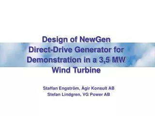
Direct-Drive Rotary Generator Design by Genetic Algorithm for Ocean Wave Energy Application. Christopher Haller Graduate Research Assistant Oregon State University haller@eecs.oregonstate.edu. Hai-Yue Han Graduate Research Assistant Oregon State University haiyuehan@gmail.com.

E N D
Direct-Drive Rotary Generator Design by Genetic Algorithm for Ocean Wave Energy Application Christopher Haller Graduate Research Assistant Oregon State University haller@eecs.oregonstate.edu Hai-Yue Han Graduate Research Assistant Oregon State University haiyuehan@gmail.com Dr. Ted K.A. Brekken, Ph.D. Assistant Professor Oregon State University brekken@eecs.oregonstate.edu Dr. Annette von Jouanne, Ph.D. P.E. Professor Oregon State University avj@eecs.oregonstate.com Research Conducted: June - September 2009 Presentation: October 5, 2009
Presentation Outline Wave Energy Background Design Considerations Mechanical Layout Time Domain Electromagnetic Analysis Conclusion
2007 10kW Seabeav I • 11 foot spar • 4 foot diameter float • Designed for water depth of 135 feet
2007 10kW Seabeav I Preparing for sea trial in Newport [5]
2008 10kW L-10 • 25 feet tall, 11 feet wide • Direct Drive • Integrated Linear Generator • No pneumatics or hydraulics • Developed in collaboration • with C.P.T. and the Navy
OSU Facilities to Advance Wave Power Wallace Energy Systems and Renewables Facility (WESRF) O.H. Hinsdale Wave Research Lab (HWRL)
750 KVA Adjustable Power Supply • Variable Voltage input(0-600Vac), 600A • 3-phase adjustable (while loaded) for balanced and unbalanced testing • Highest Power University Lab in the Nation • Enables Multi-Scale energy research • Four Quadrant Dynamometer • Programmable torque/speed • Dynamic Vector Controls 0-4000 rpm • Bidirectional Grid Interface • Regeneration back to the utility grid • Flexible, 300 hp,Motor/Generator test-bed • 120KVA programmable source • Transient VLrms=680V • Steady State VLrms= 530V • Frequency range: 45Hz to 2KHz • 10 kW Linear Test Bed • 2 m/s, 10 kN • 1 ms/, 20 kN OSU – Key Location for Wave Power Research Wallace Energy Systems and Renewables Facility (WESRF)
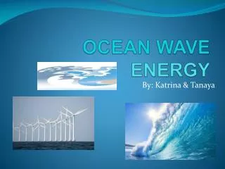
Why Wave Energy? • Wind Energy → 587 W/m2 with 8 m/s mean distribution of wind speed • Solar Energy → 200 W/m2 Year Round Average • Wave Energy → 30kW/m Year-Round-Average Available [2,3,4]
Why Wave Energy? Wave Power Density in Kilowatts per Meter [kW/m] [1]
Design Considerations • Low Speed Operation (5 rpm) • Reciprocating Rotary Design • High Torque Load • Caustic Ocean Environment • Serviceability Complications
Top Level Design Choices Characteristics • Axial / Radial • Super Conductor • Crescent Shaped • Air / Iron Core Machines Considered PMAC Doubly Fed Induction Induction Reluctance Vernier Hybrid
Three-Phase Coil Configuration Cross-Sectional Top-Down View
Simplified Magnetic Circuit Calculation Methods • Magnetic Circuit Analysis • Magnetic Shear Line to 2nd Quadrant B-H Operation intercept
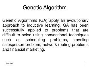
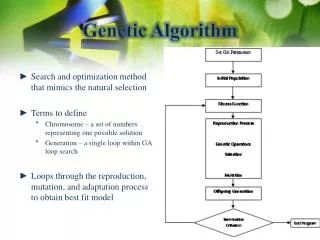
Initial population created. • Population doubled. • Random cross breeding between 1st and 2nd population set • Random mutations w/ fixed-rate / fixed-probability (quantity) • All genes saturation checked / adjusted. • Fitness of chromosomes evaluated, sorted from best to worst. • Worst ½ of chromosomes discarded, repeat back to doubling. • Best motor tracked throughout process. Initial Genetic Algorithm
Time Domain Refinement • Maximum allowable turns in air-gap. • Steel thickness based upon allowed flux density. • Many safety/saturation checks removed. • Processing speed 4.3 times faster than previous model.
Genetic Algorithm Cost Functions • {Negative numbers indicate a “more fit” machine} • -Total Power • -Total Power, -Efficiency, +Steel Volume • -Total Power, -Efficiency, + Total Mass, +AWG, +Wire Turns • -Total Power, Efficiency, +Total Mass, +AWG Size, Wire Turns • Used for final evaluation: • -Total Power, -Efficiency, +Total Mass, +Magnet Volume
Parametric Sweep of 5 Genes • Swept 25 steps nested sweep. • 9,765,625 evaluations. • 1.5x the run time of the refined (2nd) design, 2.8x slower run time of original design (1st). • Evaluated with GA cost function for fitness. • Results different from GA.
Conclusions: • 5 [rpm] generator is feasible. • Generator possible, but heavy. • Weight and slow speed lead to issue of cost. • Future Work Direction: • Examine larger variety of motor topologies. • Perform more in-depth cost analysis. • Refinements to manufacturability. Conclusions & Future Work
Bibliography [1] http://www.geni.org/globalenergy/library/renewable-energy-resources/ocean.shtml Global Energy Network Institute [2] http://blogs.mysanantonio.com/weblogs/clockingin/wind%20turbine.jpg [3] http://venturebeat.com/wp-content/uploads/2009/07/solar-panel-1.jpg [4] http://eecs.oregonstate.edu/wesrf/projects/images/Wave%20Energy_Final.ppt [5] Steven Ernst. Personal interview, 2009. Oregon State University. [6] Duane C. Hanselman. Brushless Permanent-Magnet Motor Design, 1994. [7] Magcraft. Permanent magnet selection and design handbook. National Imports, April 2007. [8] Ned Mohan. Electric Drives: An Integrative Approach, 2003. [9] Joseph Prudell. Email, 2009. Oregon State University. [10]Joseph Prudell. Novel design and implementation of a permanent magnet linear tubular generator for ocean wave energy conversion, 2007. Thesis for Master of Science. [11] P.C. Sen. Principles of Electric Machines and Power Electronics, 1997. [12] Mueller & McDonald. A Lightweight Low Speed Permanent Magnet Electrical Gen- erator for Direct-Drive Wind Turbines, 2008.
Thanks to Grainger Center for Electric Machinery and Electromechanics for supporting this research. Acknowledgement