Download
1 / 15
150 likes | 252 Views
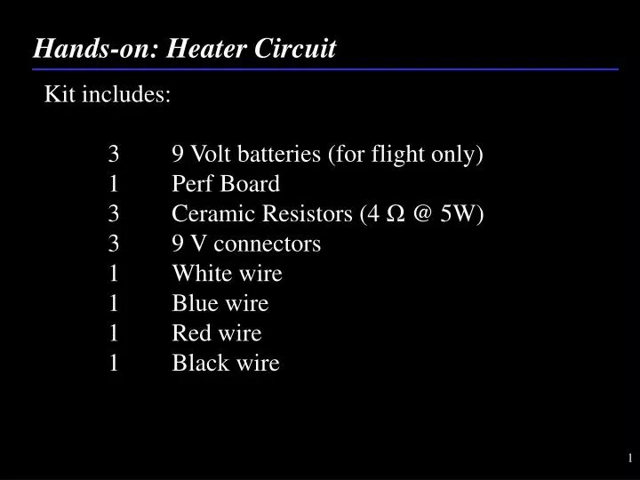
Hands-on: Heater Circuit. Kit includes: 3 9 Volt batteries (for flight only) 1 Perf Board 3 Ceramic Resistors (4 Ω @ 5W) 3 9 V connectors 1 White wire 1 Blue wire 1 Red wire 1 Black wire. Hands-on: Heater Circuit. 1. Set out kit . Hands-on: Heater Circuit.

E N D
Hands-on: Heater Circuit Kit includes: 3 9 Volt batteries (for flight only) 1 Perf Board 3 Ceramic Resistors (4 Ω @ 5W) 3 9 V connectors 1 White wire 1 Blue wire 1 Red wire 1 Black wire
Hands-on: Heater Circuit 1. Set out kit
Hands-on: Heater Circuit 2. Layout Resistors on PerfBoard Front: Back:
Hands-on: Heater Circuit 3. Fold the leads of two of the resistors and solder them together as shown:
Hands-on: Heater Circuit 4. Clip the leads:
4Ω 4Ω 4Ω Hands-on: Heater Circuit 5. Repeat steps 3 and 4 so the resistors are soldered in series, using the leads of the resistors
Hands-on: Heater Circuit Your circuit should look like this:
Hands-on: Heater Circuit 6. Twist all the Red wires from the 9V connector together and solder them to the single red wire in your kit
Hands-on: Heater Circuit 7. Twist all the Black wires from the 9V connector together and solder them to the single black wire
Hands-on: Heater Circuit 8. Check continuity for all “-” and “+” terminals to each other
Hands-on: Heater Circuit 9. Check continuity for all “+” terminals of the battery with the end of the single RED wire 10. Check continuity for all “-” terminals of the battery with the end of the single BLACK wire
Hands-on: Heater Circuit 11. Put electrical tape on solder joints
4Ω 4Ω 4Ω Hands-on: Heater Circuit 12. Solder the single RED wire from 9V connector to one end of the resistor string and the WHITE wire to the other end of the resistor string *Green boxes are battery connectors
4Ω 4Ω 4Ω Hands-on: Heater Circuit 13. Solder the switch in between the black wire and the white wire
4Ω 4Ω 4Ω Hands-on: Heater Circuit 14. Test your finished Heater by turning on the switch and putting your finger on the resistors – if they get warm, you’re done. If they don’t, check continuity at the following points: