Download
1 / 27
270 likes | 363 Views
Unique Features and Requirements for The Optical Layer Control Plane. <draft-chiu-strand-unique-olcp-01.txt> IETF49 IPO WG, August 2000 Angela L. Chiu John Strand AT&T Labs Bob Tkach Celion Networks. Objectives of Our Draft.

E N D
Unique Features and Requirements for The Optical Layer Control Plane <draft-chiu-strand-unique-olcp-01.txt> IETF49 IPO WG, August 2000 Angela L. Chiu John Strand AT&T Labs Bob Tkach Celion Networks
Objectives of Our Draft • Describe unique features and requirements of the Optical Layer and services • Constraints on routing • Design of network elements • Impairment constraints in all-optical networks • Diverse routing • Business and operational realities • Point out impacts on Optical Layer control plane (OLCP) design and routing
Design of Network Elements • Reconfigurable network elements in the Optical Layer include OLXC’s, OADM’s, tunable lasers, etc. all-optical subnetwork Figure 1: An Optical Transport System (OTS) with OADM's • Adaptation: functions at the edges that transform the incoming optical channel into the physical l to be transported through the subnetwork • Connectivity: defines which pairs of edge Adaptation functions can be interconnected through the subnetwork
Impacts of Adaptation and Connectivity • Multiplexing: Either electrical or optical TDM may be used to combine the input channels into a single l. • Adaptation Grouping: Groups of k (e.g., 4) l’s are managed as a group within the system and must be added/dropped as a group • Laser Tunability: The lasers producing the LR l’s may be tunable over a limited range, or be tunable over the entire range of l’s supported by the DWDM. Tunability speeds may also vary. => constrained connectivity between adaptation functions
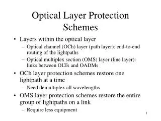
Impairment Constraints in Transparent Subnetworks Opaque vs. transparent: • Opaque: each link is optically isolated by expensive transponders doing O/E/O conversions from other links • Transparent: all-optical, bit rate and format independent • Advantages: cost saving, upgrade flexibility, etc. • Disadvantage: accumulation of physical impairments • Not all paths through a transparent subnetwork is feasible in general Objective: allow expansion of “domain of transparency” with proper routing =>Need to consider physical impairmentsincluding Polarization Mode Dispersion (PMD), Amplifier Spontaneous Emission (ASE), and others
Nl Kl Jl Ll PMD OADM OADM OADM OA OA OA B \ DPMD 0.5 ps/km 0.1 ps/km 10Gb/s L<400km L<10000km 40Gb/s L<25km L<625km • 10Gb/s or lower: not an issue except for bad fibers • 40Gb/s or higher: will be an issue Nl PMD < a% bit duration (a=10) => DPMD(k) & L(k): : PMD parameter & length of the kth span, k=1, .., M L: total length of a transparent segment
ASE Bit rate & transmitter-receiver technology (e.g., FEC)=>SNRmin w/ unity gain => • Assuming signal power PL=4dBm, amplifier gain G=25dB, excess noise factor nsp=2.5,, hB0=-58dBm w/ carrier freq. and optical BW B0 • With FEC, SNRmin=20dB => M 10 • Without FEC, SNRmin=25dB => M 3
Other Polarization Dependent Impairments • Other polarization-dependent effects besides PMD influence system performance. • For example, many components have polarization-dependent loss (PDL) which accumulates in a system with many components on the transmission path. • The state of polarization fluctuates with time, and it is generally required to maintain the total PDL on the path to be within some acceptable limit.
Chromatic Dispersion • For reasonably linear systems, there are reasons to believe that this impairment can be adequately (but not optimally) compensated for on a per-link basis.
Nonlinear Impairments • It seems unlikely that these can be dealt with explicitly in a routing algorithm because they lead to constraints that can couple routes together and lead to complex dependencies, e.g. on the order in which specific fiber types are traversed. • A full treatment of the nonlinear constraints would likely require very detailed knowledge of the physical infrastructure, including measured dispersion values for each span, fiber core area and composition, as well as knowledge of subsystem details such as dispersion compensation technology. • This information would need to be combined with knowledge of the current loading of optical signals on the links of interest to determine the level of nonlinear impairment.
Nonlinear Impairments (cont.) • Alternatively, one could assume that nonlinear impairments are bounded and increase the required OSNR level (SNRmin) by X dB, where X for performance reasons would be limited to 1 or 2 dB, consequently setting a limit on route length. • For the approach described here to be useful, it is desirable for this length limit to be longer than that imposed by the constraints which can be treated explicitly. • It is possible that there could be an advantage in designing systems which are less aggressive with respect to nonlinearities, and therefore somewhat sub-optimal, in exchange for improved scalability, simplicity and flexibility in routing and control plane design.
Implications For Routing and Control Plane Design • Additional state information will be required by the routing algorithm for each type of impairment that has the potential of being limiting for some routes, e.g., DPMD(k), L(k), G(k),nsp(k) and X dB, or in some aggregated fashion. • The specific constraints required in a given situation will depend on the design and engineering of the domain of transparency; for example it will be important to know whether chromatic dispersion has been dealt with on per-link basis, and whether the domain is operating in a linear or nonlinear regime.
Implications (cont.) • It is likely that the physical layer parameters do not change value rapidly and could be stored in some database; however these are physical layer parameters that today are frequently not known at the granularity required. If the ingress node of a lightpath does path selection these parameters would need to be available at this node. • In situations where only PMD and/or ASE impairments are potentially binding the optimal routing problem with the two constraints, OSPF algorithm enhancements will be needed. However, it is likely that relatively simple heuristics could be used in practice.
Diverse Routing • Key requirement for • Optical layer protection/restoration • Higher layer restoration, e.g., IP reroute for link failure • "Shared Risk Link Group" (SRLG): relationship between two non-diverse links, incl. many Types of Compromise: • Examples: shared fiber cable, shared conduit, shared ROW, shared optical ring, shared office without power sharing, etc. • Impacts on control plane: nodes need to propagate information of • Number of channels available for each channel type (e.g., OC48, OC192) on each channel group • Channel group: a set of channels that are routed identically and should be given unique identification. • Each channel group can be mapped into a sequence of fiber cables while each fiber cable can belong to multiple SRLG’s based on their definitions.
Other Unique Features • Bi-directionality: channel contention issue • Protection/restoration: • A pre-established protection path does occupy ports and wavelengths =>not optimized for shared mesh protection across different endpoints
Business and Operational Realities • Expensive & periodically scarce optical network resources and equipments => critical to control network access, measure and bill for usage • Support legacy services => multiple client types besides IP routers • Heterogeneity: • May across multiple carriers incl. Local Exchange Carriers & national networks, may across trust boundaries • Transparent vs. opaque • Ring vs. mesh protection/restoration • Introduction of new technology => vendor specific design/constraints • Different max. supportable bit rates
Business and Operational Realities (cont.) • Requirement: design a control plane that is flexible and extendable to support end-to-end fast provisioning, reconfiguration, and protection/restoration across heterogeneous subnetworks • Task: design scalable information exchange between subnetworks using extension of routing protocols in the control plane • Service requirements being defined in OIF by the Carrier Subgroup (chaired by John Strand of AT&T) -> IETF
Discussions on Control Plane Architecture • Today’s OTS is a simple “domain of transparency” consisting of WDM Mux/Demuxers and Optical Amplifiers. Because an OTS is not easily reconfigurable today, these constraints are dealt with at the time of installation and don’t complicate routing and the control plane. • As domains of transparency become both larger and software reconfigurable, these physical constraints on connectivity and transmission quality become increasingly of concern to the control plane. • The evolution is largely technology driven => heterogeneous technologies => different in their routing implications.
Control Plane Architecture Alternatives Per-domain routing: • Each domain could have its own tuned approach to routing. • Inter-domain routing would be handled by a multi-domain or hierarchical protocol that allowed the hiding of local complexity. • Single vendor domains might have proprietary intra-domain routing strategies.
Control Plane Architecture (cont.) Enforced Homogeneity: • The capabilities of the control plane would impose constraints on system design and network engineering. • As examples: if control plane protocols did not deal with nonlinear impairments carriers would require their vendors to provide transport systems where these constraints were never binding. • Transmission engineers could be required to only deploy domains where every possible route met all constraints not handled explicitly by the control plane even if the cost penalties were severe.
Control Plane Architecture (cont.) Additional Regeneration: • At (selected) OLXC’s within a domain of transparency, the control plane could insert O/E/O regeneration into routes with transmission problems. • This might make all routes feasible again, but at the cost of additional cost and complexity and with some loss of rate and format transparency.
Control Plane Architecture (cont.) Standardized Intra-Domain Routing Protocol: • A single standardized protocol which tries to deal with the full range of possible topological and transmission constraints will be extremely complex and will require a lot of state information. • However when combined with limited application of the two previous approaches it might be more plausible.
Centralized vs Distributed Routing • A centralized routing model, where routing is done centrally using a centralized database with a global network view would be suitable for a domain where DWDM transmission systems have reconfigurable OADMs in between terminating points and tunable lasers on the drop ports. • A distributed model appear to be an excellent candidate for a purely "opaque" domain where impairment constraints play no role in routing.
Advantages of Centralized Routing • Information such as SRLG’s and performance parameters which change infrequently and are unlikely to be amenable to self-discovery could reside in a central database and would not need to be advertised. • Routing dependencies among circuits (to ensure diversity) is more easily handled centrally when the circuits do not share terminals since the necessary state information should be more easily accessible in a centralized model. • Pre-computation of restoration paths and other computations that can benefit from the use of global state information may also benefit from centralization.
Disadvantages of Centralized Routing • If rapid restoration is required, it is not possible to rely on a centralized routing system to compute a recovery path for each failed lightpath on demand after a failure has been detected. The distributed model arguably will not have this problem. • The centralized approach is not consistent with the distributed routing philosophy prevalent in the Internet. The reasons which drove the Internet’s architecture – scalability, the inherent problems with hard state information, etc. – are largely relevant to optical networking. • A centralized approach would seem to preclude integrated routing across the IP and optical boundary.
Pre-Computing All Possible Routes Advantage: allowing more sophisticated algorithms to be used to filter out the routes violating transmission constraints. Disadvantages: • In a large national network there are just too many routes that might be needed, by orders of magnitude. This is particularly true when diversity constraints and restoration routing may force weird routings. • Every time any parameter changes anywhere in the network all routes using the impacted resource will need to be reexamined.
Next Steps • Propose to make this a WG document • Work with vendors and other carriers to propose standardized solutions for those that have not been properly addressed by existing protocols