Download
1 / 42
420 likes | 728 Views
LPW Booms. Jeremy McCauley Aerospace Engineer Space Sciences Laboratory, UCB jeremymc@ssl.berkeley.edu. LPW Boom Overview. Design Drivers Design Description Concept Heritage Assembly Breakout Thermal ETU Integration and Testing (I&T) (Backup Slides). LPW Boom Design Drivers.

E N D
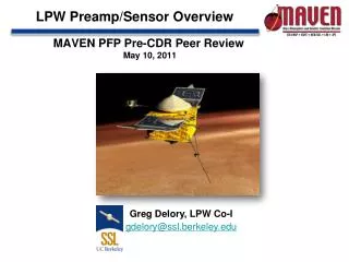
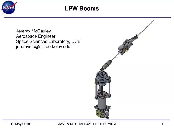
LPW Booms Jeremy McCauley Aerospace Engineer Space Sciences Laboratory, UCB jeremymc@ssl.berkeley.edu MAVEN MECHANICAL PEER REVIEW
LPW BoomOverview • Design Drivers • Design Description • Concept • Heritage • Assembly Breakout • Thermal • ETU Integration and Testing (I&T) (Backup Slides) MAVEN MECHANICAL PEER REVIEW
LPW BoomDesign Drivers • Deploy Langmuir Probe antenna with associated preamplifier 7 meters from rest position on spacecraft. • Interface to spacecraft to support deployable booms and antennas in stowed configuration. • Meet alignment requirement (< 1.43° radial). • Provide a connector for test input to the sensor accessible during all integration phases. • Total Mass NTE 6.12 kg (Each AXB Unit NTE 3.06kg) • Interface Operational Temperature Range: -35 to +70C (PF) • Interface Survival Temperature Range: -50 to +70C (PF) MAVEN MECHANICAL PEER REVIEW
LPW BoomConcept • Boom Unit • Sensors Extended from SC on Stacers • Compact for Launch • Rigid after Deploy MAVEN MECHANICAL PEER REVIEW
LPW BoomHeritage • Heritage Unit • Primarily AXB from RBSP, modified for length and to fit MAVEN SC • Structure, Stacer, Spool, Whip, Cage, DAD design and springs • Braking Mechanism from STEREO WAVES • Similar to units on RBSP (4), THEMIS (10), STEREO (6), POLAR and FAST • More than 60 years of on orbit operation MAVEN MECHANICAL PEER REVIEW
LPW BoomOrder of Deploy • Stowed Unit • Unpowered • Fully Restrained • Step 1: Whip Deploy • Frangibolt Actuated • Spring Powered Deploy Axis • Step 2: Stacer Deploy • Frangibolt Release • Stacer Driven • Retarded by Braking Mechanism to ~1 m/s MAVEN MECHANICAL PEER REVIEW
LPW Boom Design Description • Overall Design • Two (2) Identical Boom Units • Stationary Deploy Assembly • Moving DAD • Stacer • Preamp and Whip MAVEN MECHANICAL PEER REVIEW
LPW Boom Design Description Stowed Configuration • Boom Design • Stationary Deploy Assy • Moving DAD • Stacer • Preamp and Whip Whip Preamp Deploy Assy Stacer DAD Deployed Configuration MAVEN MECHANICAL PEER REVIEW
LPW Boom Design Description Stowed Configuration • Stationary Deploy Assy • Caging Mechanism • Spool and Brake Assembly • Roller Nozzle #1 Spool and Brake Assy Roller Nozzle #1 Caging Mechanism Deployed Configuration MAVEN MECHANICAL PEER REVIEW
LPW Boom Design Description Stowed Configuration • Caging Mechanism • Release Whip on Orbit • Frangibolt Actuator (Next Slide) • Top Opens • ReleasesWhip • DAD Plunger with Kickoff Spring Starts Whip • Test Contact for Ground Operations • Torque Margin: 40.9 (RBSP) • Spring to Friction Drag DAD Plungers Test Contact Frangibolt Deployed Configuration MAVEN MECHANICAL PEER REVIEW
LPW Boom Design Description: Frangibolt • TiNFrangibolt • 500 lb Retention Force • For Launch Loads Only • Static Margin: 14 • Resettable • 25 W @ 28 Vdc • 95°C Actuation Temperature MAVEN MECHANICAL PEER REVIEW
LPW Boom Design Description Frangibolt Harness Slip Ring Spool Brake Sense Switches • Spool and Brake Assembly • Stacer Frangibolt Release • Harness Spool: Max Capacity 7.22 meters 0.096” diameter cable • Sense Switches: Stacer Release and Turn Counter (Newark, 1HM1) • Slip Ring (Airflyte CAY-1398) • Length Resolution: 4 clicks/turn • Torque Margin: TBD (Stacer Force to Bearing Friction) MAVEN MECHANICAL PEER REVIEW
LPW Boom Cable Load Path Glue Joint • Cable Force Path • Force is carried completely in Kevlar overwrap • Static Margin: >100 Tie Off Point MAVEN MECHANICAL PEER REVIEW
LPW Boom Design Description • Roller Nozzle #1 • Centering of the Stacer • Resist SC Forces • Springs designed to 1.6 lb minimum radial force Rollers Rocker Arms MAVEN MECHANICAL PEER REVIEW
LPW Boom Design Description • Moving DAD • Deployment Assist Device (DAD) with Kickoff Springs • Lock Wheel Assemblies • Increase Unseat Force from 6 lbs to 15 lbs axial from 1.6 to 4.5 lbs radial • Roller Nozzle #2 • Springs designed to 1.6 lb minimum radial force • Force Margin: 2.1 • DAD Springs to Friction Roller Nozzle #2 DAD Springs Lock Wheel Assy Stowed Configuration Deployed Configuration MAVEN MECHANICAL PEER REVIEW
LPW Boom Design Description • Stacer • Helical Spring • Deployed Acts as a Rigid, Thin-walled Tube • Force Margin: > 3 (RBSP) • Stacer Force to Friction Deployed Configuration Stacer MAVEN MECHANICAL PEER REVIEW
LPW Boom Design Description MAVEN MECHANICAL PEER REVIEW
LPW BoomGlue Bond Margins * Joint Strength is derated according to surface preparation requirements as discussed in HTN-102050-017, dated 06/15/2000, as received from Chris Smith, UCB/SSL. ** Negative Force values indicate the joint is in compression. MAVEN MECHANICAL PEER REVIEW
LPW BoomGlue Bond Margins DAD Rod to DAD Tip Tip Tube to Tip End Tip to Tip Tube Tip to Safety Pin MAVEN MECHANICAL PEER REVIEW
LPW Boom Design Description • Hinge, Whip and Preamp • Hinge • Torque Margin: 3.6 (RBSP) • Hinge Spring to Friction • DAG 213 Coated • Preamp • Probe and Preamp Assy • DAG 213 Coated • Whip Tube • Titanium • FOS (Bending on Deploy): 5.9 • TiNCoated • Cannot Clean DAG 213 or TiNsurfaces • All Three Isolated for Potential Control Whip Preamp Hinge Deployed Configuration MAVEN MECHANICAL PEER REVIEW
LPW Boom Design Description • Hinge, Whip and Preamp • Hinge • Torque Margin: 3.6 (RBSP) • Hinge Spring to Friction • DAG 213 Coated • Preamp • Probe and Preamp Assy • DAG 213 Coated • Whip Tube • Titanium • FOS (Bending on Deploy): 2.0 • TiNCoated • Cannot Clean DAG 213 or TiNsurfaces • All Three Isolated for Potential Control Whip Preamp Hinge Deployed Configuration MAVEN MECHANICAL PEER REVIEW
LPW Boom Design Description: Thermal (TBC) • Thermally Coupled to the SC • Whip • Coated with TiN • Stacer, Hinge, and Preamp: • Coated with DAG 213 • Stationary Deploy Assy and Moving DAD: • Alodine (Gold) • Electroless Nickel Plating with Teflon Impregnate MAVEN MECHANICAL PEER REVIEW
LPW BoomHidden Items • Mate of JH to PH • During assembly of Whip to Stacer Tip Piece • The mate is hidden • Alignment is checked beforehand • Harness is checked afterward MAVEN MECHANICAL PEER REVIEW
LPW Boom Design Description: Stress Margins MAVEN MECHANICAL PEER REVIEW
LPW BoomDesign Spreadsheets • Caging Spring Torque • DAD Lock Spring • DAD Telescoping Spring • Frangibolt Firing Times • Hinge CTE • Hinge Spring Torques • Large Fine Pitch Bolt Torques • Mass Properties • Roller Nozzle Spring • Sense Line Resistances • Whip Torsion Spring • Wire and Spool MAVEN MECHANICAL PEER REVIEW
EFW AXBLong Lead Items Frangibolts To Be Ordered ~10 week lead Gore Cable Quote in Progress Stacer Ordered ~22 week lead time
LPW Boom Design Description • Back up slides • Redundancy is Key…. MAVEN MECHANICAL PEER REVIEW
SSL History / Heritage UCB/SSL HERITAGE(courtesy F. Mozer) Spacecraft SPB’s AXB’s Mag Booms S3-2 4 S3-3 4 2 ISEE 2 VIKING 4 FREJA 6 FIREWHEEL* 2 CRRES 2 POLAR 4 2 FAST 4 2 2 CLUSTER I* 16 CLUSTER II 16 THEMIS 20 10 10 SPARES 26 6 2 Lunar Prospector 1 Sounding Rockets ~50 ----- ----- ----- 110 26 (+ 50) 15 * LAUNCH FAILURE 10 May 2010 MAVEN MECHANICAL PEER REVIEW
LPW Boom Design Description: Materials • Materials and Properties Assumed • Metals, Yield Stress: • Brass 360, 49 kpsi • Aluminum, 2024-T8, 58 kpsi • Aluminum, 2117-T4, 24 kpsi • Aluminum, 5052-H32, 28 kpsi • Aluminum, 6061-T6, 40 kpsi • Beryllium Copper, #25 (C17200), 160 kpsi • Bronze C544, 35 kpsi • Copper (Oxygen-free, C10100), N/A • Elgiloy, Spring Temper • Steel, SS, 18-8, 70 kpsi • Steel, SS, 300 Series, 30 kpsi • Steel, SS, 400 Series, N/A • Steel, SS, 17-7 PH, CH900, C condition, 230 kpsi • Tantalum per ASTM-B365-98, 65 kpsi (Ultimate) • Titanium, 6Al-4V, 120 kpsi MAVEN MECHANICAL PEER REVIEW
LPW Boom Design Description: Materials • Materials and Properties Assumed • Plastics: • Acrylic (Medium-high impact), 6kpsi • Black Delrin, 11 kpsi (Ultimate) • White Delrin, 11 kpsi (Ultimate) • Vespel SP3, 8 kpsi (Ultimate) • PEEK 450G, 14.1 kpsi MAVEN MECHANICAL PEER REVIEW
LPW Boom Design Description: Materials • Materials and Properties Assumed • Adhesives: • Hysol 9309NA, 4 kpsi (Tensile shear Strength) • Hysol 0151 • 3M EA1838 • 3M EA 2216 • Tapes: • Kapton Tape (acrylic adhesive) • Lubricants: • Braycote 601 –or— Braycote 601 EF • DAG 154 Paint MAVEN MECHANICAL PEER REVIEW
LPW Boom Design Description: Materials • Coatings Used • Alodine per MIL-C-5541 CL 3 (Gold) • Black Anodize per MIL-A-8625 Type II, Class 2 • Hard Black Anodize per MIL-A-8625 Type III, Class 2 • Electroless Nickel Plating with Teflon Impregnate • Silver Plate per QQ-S-365 Type I, Grade A • Gold Plate per MIL-G-45204 CL 1 TYPE II, Bright Finish • Braycote 601 –or— Braycote 601 EF • DAG154 Paint • DAG213 Paint • TiN MAVEN MECHANICAL PEER REVIEW
LPW Boom Design Requirements • Mechanical Design Requirements • From MAVEN-SYS-RQMT-0010 ERD, Rev. - • MAC Limit Load: ~55 g (3 kg) • Factors of Safety: See Chart • Provide a fundamental frequency of greater than 100 Hz (Stowed). • Model Uncertainty Factor (MUF): 1.25 to 1.4 • Yeilds: 86 g (Limit Load) MAVEN MECHANICAL PEER REVIEW
LPW Boom Design Description: I&T MAVEN MECHANICAL PEER REVIEW
LPW Boom Design Description: I&T • Functional Deployments • Expected number of deployments on the instrument at launch: 4 • Functional • Post Vibe Functional • Thermal Vacuum Hot • Thermal Vacuum Cold • Deployments of Whip and Cage at SC Level after Vibe All stacer deployments include: Frangibolt trending, Continuity verification, Runout and Stiffness testing. MAVEN MECHANICAL PEER REVIEW
LPW Boom Design Description: I&T • ETU Flow: Alignment Testing • Requirement: 1.43° total error • Previous Baseline: (RBSP) • Testing Total: <2.2” @ 6m length or <0.5° error from Boom • Stacer Runout is <1.2” (0.88”, 0.73”, 1.2”, 1.2”, 0.94”) • Unit deployed horizontally on a g-negating track, then lifted to floats. • RSS Analysis of Tolerance Stackup: 0.20 degree (0.8 inches at Sphere) • Hinge, Whip and Sphere Runout is <0.1” • Loose Stacer on Tip 0.1” • Stiffness: 0.003 lb/in • Fund. Frequency: 0.43 Hz(0.25 Hz Conservative Estimate for LPW) MAVEN MECHANICAL PEER REVIEW
LPW Boom Design Description: I&T • ETU Flow: Stiffness Testing • Slope: 0.003 lb/in inches grams MAVEN MECHANICAL PEER REVIEW
LPW Boom Design Description: I&T • Stacer Fundamental Frequency Testing • Unit deployed horizontally, then tested horizontally in Runout Test Fixture. • RBSP ETU Unit: 0.43 Hz MAVEN MECHANICAL PEER REVIEW
LPW Boom Design Description: I&T • ETU Flow: Vibration Testing • Vibration to Qualification levels per MAVEN-SYS-RQMT-0010 ERD, Rev. -, Appendix, Table 24 (Below) • Self-shock survival from boom deployment actuations • Force Limiting • First Frequency: X, Y = TBD Hz, Z = TBD Hz MAVEN MECHANICAL PEER REVIEW
LPW Boom Design Description: I&T • ETU Flow: Thermal Vacuum Testing • per the requirements and limits indicated in MAVEN-SYS-RQMT-0010 ERD, Rev. - • Deployment tests at hot and cold levels • Whip and Caging Mechanism deployment testing performed at the subassembly level • Stacer deployment performed at the assembly level • Unit will be deployed horizontally on a g-negating track within the Thermal Vacuum Chamber • Preamplifiers will be separately tested. HOT DEPLOY COLD DEPLOY MAVEN MECHANICAL PEER REVIEW
LPW Boom Mass Properties Testing • Mass Properties Testing: to be completed • Measure: CG, MOI Stowed • Analysis: CG, MOI Deployed MAVEN MECHANICAL PEER REVIEW
This page intentionally almost blank MAVEN MECHANICAL PEER REVIEW