Download
1 / 53
580 likes | 855 Views
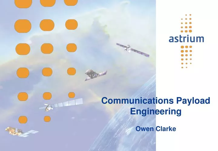
Communications Payload Engineering Owen Clarke. Aims. To describe the main components of the Communications satellite payload and explain how designs are impacted by the changing needs of the user. Contents. Introduction Payload Function Payload Constraints Payload Specifications

E N D
Communications Payload Engineering Owen Clarke
Aims To describe the main components of the Communications satellite payload and explain how designs are impacted by the changing needs of the user EADS Astrium
Contents • Introduction • Payload Function • Payload Constraints • Payload Specifications • Payload Configurations • Payload Equipment EADS Astrium
Communications Payload Function Transmit Antenna Receive Antenna Repeater Uplink Downlink Communications Payload = Antenna Sub-System + Repeater EADS Astrium
Essential Communication Payload Functions • Antenna Functions • To provide highly directional receive and transmit beams • Repeater Functions • Power Amplification • Frequency Conversion EADS Astrium
Antenna Types and Functions • Reflector Antennas • Parabolic Reflector with Off-set Feed • With Gregorian or Cassegrain Sub –reflector • Gridded Reflectors for Polarisation Discrimination • Dual Gridded Assemblies for dual plane polarisation • Direct Radiating Phased Arrays • Shaped Beams • Shaped Reflector Surfaces • Multiple Feeds with Beamforming Network • Generation of Multiple Beams from the same Aperture • Reflectors with De-focused Feed Arrays EADS Astrium
Typical Repeater Functions • Receive and filter uplink signals • Provide minimum C/No degradation • Provide variable high gain amplification • Downconvert Frequency for re-transmission • Filter high power downlink signal and re-transmit • Provide high reliability in functionality • Beam-to-beam interconnectivity • Functional re-configurability • Beamforming EADS Astrium
Why Filter? • Elimination of Spurious Transmissions • Elimination of Self Interference • Elimination of Image Bands introduced by Mixing Processes • Elimination of Alias Bands before and after Sampling Processes • Partitioning of Spectrum to allow Channelised Amplification • Partitioning of Spectrum for usage by Different Services • Partitioning of Spectrum for use on Different Routes EADS Astrium
Why High Reliability? • Everyone wants machines, tools, people, services to be reliable • What is special about Communications Satellites? • Inaccessibility of the orbits used • LEO – Generally highly inclined • GEO – High altitude means: High potential energy AND High kinetic energy • Either way large high energy launch vehicles required • Very expensive to launch in the first place • Inaccessible to astronauts or remote control vehicles • Repair by external intervention virtually impossible • The design must be tolerant of internal failures EADS Astrium
Payload Constraints • Accommodation • Physical size, must fit on spacecraft platform, compatibility with launch vehicle fairing • Thermal Dissipation • Limited ability of spacecraft to radiate heat, radiator area • Mass • Impacts fuel, life, cost, functionality • Power consumption • Impacts thermal design, mass of power sub-system • Thermal Control • Comms. performance versus mass of thermal control hardware • Received Noise • Thermal noise • Transmitter Noise • Includes: Passive Intermodulation, Multipaction Noise EADS Astrium
Quality of the Receive System – G/T • The quality of the satellite receive system, in terms of its ability to receive a given signal with a high signal to noise ratio is usually expressed as:Ga/ Ts • Where: Ga = Antenna Gain (Relative numerically to that of an isotropic radiator and referenced to an arbitary interface at the output of the antenna) Ts = The Noise Temperature of the complete System (Referenced to the same interface at the output of the antenna) EADS Astrium
Noise Temperature • Concatenation of Noise Sources • Ts = Noise Temperature of the Complete System • Ts = Ta + T1 + T2 / G1 + T3 / (G1.G2) + T4 / (G1.G2.G3) ……... • Ta = Antenna Noise Temperature 1 2 3 4 EADS Astrium
E.I.R.P. Effective Isotropic Radiated Power EIRP = (Gain of Transmit Antenna)x(Transmit Power) EADS Astrium
Payload Constraints • Spurious Products • Mixing products: From Frequency Converters • Intermodulation products: Non linearity in active devices • Passive intermodulation products (PIMP): Transmit chain, post High Power Amplification • In Band: Directly impacts C/N0 • Out of Band: Interference to other transponders or systems EADS Astrium
Payload Constraints – Spurious Products Typical Saturation Characteristic e.g. Solid State Power Amplifier EADS Astrium
Payload Constraints – Spurious Products • Linear devices can be characterised by: Sout = aSin • Memoryless Non-linear devices can be approximated over a limited signal range by a polynomial relationship such as: Sout = a1Sin + a2Sin2 + a3Sin3 + a4Sin4 + … If 2 signals are applied such that: Sin = Asinω1t + Bsinω2t Then Sout is found to contain frequency components as follows: ω1, ω2, (ω1 - ω2), (ω1 + ω2), 2ω1, 2ω2, (2ω1 - ω2), (ω1 - 2ω2), 3ω1, 3ω2… EADS Astrium
Intermodulation Products (2) • Order of a product is m = n + k for frequency nf2 - kf1 for 2 carriers • For many closely spaced carriers, IMPs are distributed contiguously • 3rd order products most important in band • (C/I3) multi-carrier = (C/I3) 2carrier - 8 dB EADS Astrium
Intermodulation Products (3) EADS Astrium
Intermodulation Products (1) EADS Astrium
Spurious Products EADS Astrium
Transmit Filtering • Reasons for filtering after the High Power Amplifiers • To reject Out Of Band Spurious (which might adversely affect other systems) • To reject Intermodulation Noise which would fall in adjacent channels • To reject transmit noise which would fall in receive bands on the same satellite • To provide theoretically loss less recombination of amplification channels into a single signal path prior to transmission • This is achieved using an Output Multiplexer(OMUX) EADS Astrium
Payload Constraints • Transmit Characteristics • Gain v frequency • Gain slope • Gain ripple • Group delay v frequency • Group delay slope • Group delay ripple • AM/PM conversion • AM/PM transfer • AM modulation of one carrier transferred to PM modulation of another EADS Astrium
Effects of Combinations of Distortions • Gain v Frequency Slope followed by AM to PM Transfer • Results in Intelligible Cross Talk • Group Delay v Frequency Slope followed by AM to PM Transfer • Similar effects EADS Astrium
Gain Slope EADS Astrium
Group Delay Slope EADS Astrium
Payload Constraints • Electromagnetic Compatibility • Radiated and conducted • Emissions and susceptibility • Ionising Radiation • Reliability EADS Astrium
Reliability • Reliability, R, defined as: (Number of Success)/(Number of Trials) • For a single mission R = Probability of the success of the mission • Failure Rate, λ, measured in failure instances in 109 hours (FITS) • For a single mission of duration of t hours:Reliability, R, is found to be: R = e- λT where T = t/109 • For items in a functional chain (where each link must succeed for overall success): • Failure rates add to give total failure rate • Reliabilities multiply to give overall reliability EADS Astrium
Improvement of Reliability by Use of Redundancy • Probability of mission failure of an equipment is (1-R) • If a system uses 2 identical equipments in parallel, the probability of failure is the probability of both failing. This is (1-R)2 • Reliability of the system is the probability of one or none failing. • This is is 1 – (1-R)2 = 2R – R2 “Cold” Redundancy • If an equipment is switched off, λ typically decreases by a factor of ten • Thus if non-active equipments are switched off reliability can be improved further • In such a situation with a choice of 1 from 2,then RT = 11R – 10R1.1 EADS Astrium
Payload Specification EADS Astrium
Payload Configurations - Basic Elements Input Filter Low Noise Amplifier Mixer Filter Medium Power Amplifier High Power Amplifier Output Filter Local Oscillator EADS Astrium
Payload Configurations - Channelisation EADS Astrium
Payload Configurations - Redundancy Switch Network Switch Network EADS Astrium
Payload Configurations - Eutelsat 2 EADS Astrium
Payload Configurations – Inmarsat 3 EADS Astrium
Payload Configurations – Trends EADS Astrium
On-board Processing – Why? • Beamforming • Beam-to-beam interconnectivity • Improved link performance • More flexibility • Improved immunity to interference • Multi-rate communications • Reduced complexity of earth stations EADS Astrium
On-board Processing – Why Not? • Power dissipation • Mass • Thermal dissipation • Packaging • Radiation hardness • Reliability • Difficult to make “Future Proof” • Should not do processing onboard which could be done on the ground by reconfiguring the overall system EADS Astrium
Transparent Or Regenerative • Transparent • Channel to beam routing flexibility in multi-beam coverage • Uplink to Downlink frequency mapping flexibility • Channel Bandwidth flexibility • Regenerative • Independent optimisation of uplink and downlink access, modulation and coding • Link advantage through isolation of uplink and downlink noise and interference effects • Data rate conversion and signal reformatting • Packet level switching • Security features EADS Astrium
Typical Digital Processor Architecture Rx AAF A/D DEMUX LC DBFN SWITCH FRC MUX D/A AIF SSPA D/C D/C U/C 1 1 • • • • • N N • • • • • • • • • • • • • • • • • • • • • • • • Phased Array Feeder Link EADS Astrium
C-Band Tx Horn Tx C-Band Up- Converter Preprocessor & L-Band Payload Receive Section Inmarsat 4 C to L Integrity Checker C-Band Downlink L-Band L-Band Automatic Level Control Rx/Tx Rx/Tx Feed Reflector Feeder to Mobile Array C-Band Rx Horn Postprocessor & L-Band Payload Transmit Section C-Band Payload Receive Section Forward Processor C-Band Down- Converter 120 Rx 156 12 2 4 C-Band to C-Band 2 Centralised Frequency Generator 2 Mobile to Mobile LOs C-Band Payload Transmit Section 120 4 2 12 156 Return Processor Mobile to Feeder DSP Pilot Tone Injection Unit 120 L1 Navigational Payload Nav L-Band Tx Antennas L5 EADS Astrium
Payload Equipment - Receivers EADS Astrium
Payload Equipment – Multi-Chip Module (MCM) Technology EADS Astrium
Payload Equipment - Input Multiplexers EADS Astrium
Payload Equipment - Input Multiplexers EADS Astrium
Payload Equipment - Output Multiplexers EADS Astrium
Payload Equipment - Channel Amplifier EADS Astrium
Payload Equipment – Dual Travelling Wave Tube Amplifier (TWTA) Direct Thermally Radiating Type EADS Astrium
Payload Equipment - Frequency Generator EADS Astrium
Multi- Chip Module (MCM) Technology EADS Astrium
INMARSAT 4 Digital Signal Processor EADS Astrium