Download
1 / 60
790 likes | 1.26k Views
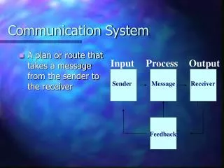
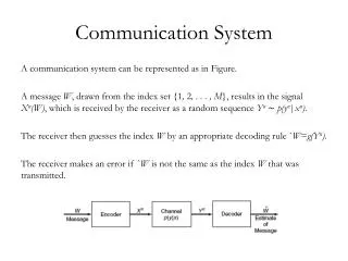
Communication system. Source encoding. Channel encoding. Line encoding. Source. Modulation. Channel. Source decoding. Channel decoding. Line decoding. Receiver. Demodulation. Distortion. Amplitude distortion Phase distortion. Insertion loss=10log 10 P 0 /P 2

E N D
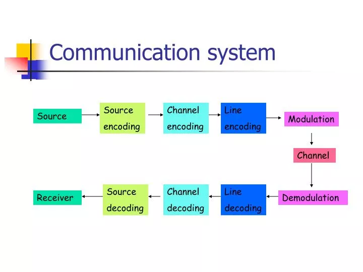
Communication system Source encoding Channel encoding Line encoding Source Modulation Channel Source decoding Channel decoding Line decoding Receiver Demodulation
Distortion • Amplitude distortion • Phase distortion
Insertion loss=10log10P0/P2 P2=Power delivered to a load by the channel P0=Power delivered to the same load without channel Amplitude response of a telephone channel
Envelope delay is the derivative of the phase shift Envelope delay and Phase response of a telephone channel
A D C B E Threshold Detector Retiming Circuit Tx Channel Equalizer Clock Extraction F Tx Rx Equalizer Threshold detector Data Clock (Trig ขาขึ้น)
Communication system Source encoding Channel encoding Line encoding Source Modulation Channel Source decoding Channel decoding Line decoding Receiver Demodulation
Data transmission • Communication modes • Simplex • Half-Duplex • Duplex or Full-duplex
Transmission modes Asynchronous transmission • Feature : unnecessary to perfectly synchronized • Encoding Technique Used : NRZ • Components : Start Bit (1 : transition from 1 to 0), Data (5-8), stop bit(1, 1.5, 2 : binary 1) • Merit : Easy-to-build • Demerit : High overhead e.g. start, stop bit 1 bit, data 8 bit -> overhead = 2/10 = 20 %
Transmission modes Synchronous Transmission • Feature : synchronized by sending timing information via separate clock line or embedding in data signal • Line coding: Manchester, AMI • Component : preamble (8-bit flag), Control, Data, Control, postamble (8-bit flag) • Merit : Low overhead comparing to Asynchronous transmission. • Example : preamble + control + postamble 48 bits • data 1000 bits -> overhead = 48/1048 = 4.6 % • data 8000 bits -> overhead = 48/8048 = 0.6 %
Transmission media Transmission medium is the physical path between transmitter and receiver in a data transmission system. • Guided vs unguided (wireless transmission) • Characteristics and quality of data communication depend on characteristics of both media and signal. • Key concern in design is data rate and distance.
Guided Transmission media • Two-wire open • Twisted pair • Coaxial cable • Fiber optic
Unguided transmission media Transport electromagnetic waves without using a physical conductor
Geostationary satellites • The satellite must move at the same speed as the earth so that it seems to be fixed above a certain spot. • Orbital speed is based on distance from the planet. • This orbit occurs at the equatorial plane and is approximately 22,000 miles from the surface of the earth. • At least 3 Satellite to cover all areas.
BW for ASK Nbaud is baud rate
Ex. Given a BW of 10,000 Hz (1,000-11,000) for a full-duplex ASK. Find the carriers and the BW in each direction. Assume there is no gap between the bands in two directions. What is the maximum baud rate and bit rate?
EXample: Find the maximum bit rates for an FSK signal if the bandwidth of the medium is 12,000 Hz, and the difference between the two carriers must be at least 2000 Hz. Transmission is in full-duplex mode.
BW for PSK • The same as ASK • Ex. Given a bandwidth of 5000 Hz for an 8-PSK signal, what are the baud rate and bit rate?
PSK is not susceptible to the noise degradation that affects ASK, nor the BW limitations of FSK.
BW for QAM • The same as ASK and PSK.
Multiplexing • multiple links on 1 physical line • common on long-haul, high capacity, links • have FDM and TDM alternatives
Wavelength Division Multiplexing • FDM with multiple beams of light at different freq • carried over optical fiber links
Data communication interfacing • DTE : Data Terminal Equipment is any device that is a source of or destination for binary digital data (PC) • DCE : Data Circuit-terminating Equipment is any device that transmits or receives data in the form of an analog or digital signal through a network (Modem) PSTN DCE DTE DTE DCE
Data communication interfacing • DTE -DCE Interfacing Requirement : Use the same encoding scheme and have common standards • Mechanical characteristics : plugs, circuits • Electrical characteristics : voltage-level, timing • Functional characteristics : meaning of each interchange circuits เช่นขา 7 คือ Ground
V.24/EIA-232 (RS 232) Electronic Industries Association (EIA)
Mechanical characteristics • (ISO 2110) 25-pin connector (but can be substituted by 9-pin (DB-9) : 8, 3, 2, 20, 7, 6, 4, 5, 22)