Download
1 / 1
10 likes | 97 Views
Robert Pushor, Catherine LeCocq, Brian Fuss, Georg Gassner Metrology Department, Stanford Linear Accelerator Center.

E N D
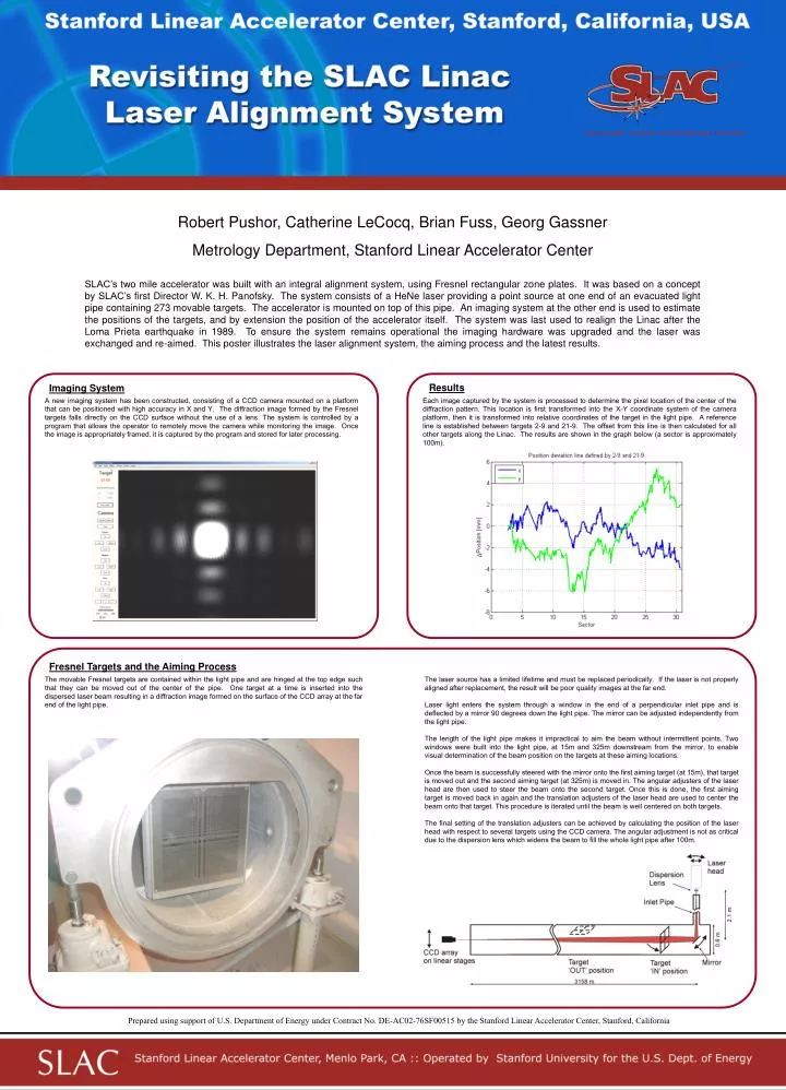
Robert Pushor, Catherine LeCocq, Brian Fuss, Georg Gassner Metrology Department, Stanford Linear Accelerator Center SLAC’s two mile accelerator was built with an integral alignment system, using Fresnel rectangular zone plates. It was based on a concept by SLAC’s first Director W. K. H. Panofsky. The system consists of a HeNe laser providing a point source at one end of an evacuated light pipe containing 273 movable targets. The accelerator is mounted on top of this pipe. An imaging system at the other end is used to estimate the positions of the targets, and by extension the position of the accelerator itself. The system was last used to realign the Linac after the Loma Prieta earthquake in 1989. To ensure the system remains operational the imaging hardware was upgraded and the laser was exchanged and re-aimed. This poster illustrates the laser alignment system, the aiming process and the latest results. Results Imaging System A new imaging system has been constructed, consisting of a CCD camera mounted on a platform that can be positioned with high accuracy in X and Y. The diffraction image formed by the Fresnel targets falls directly on the CCD surface without the use of a lens. The system is controlled by a program that allows the operator to remotely move the camera while monitoring the image. Once the image is appropriately framed, it is captured by the program and stored for later processing. Each image captured by the system is processed to determine the pixel location of the center of the diffraction pattern. This location is first transformed into the X-Y coordinate system of the camera platform, then it is transformed into relative coordinates of the target in the light pipe. A reference line is established between targets 2-9 and 21-9. The offset from this line is then calculated for all other targets along the Linac. The results are shown in the graph below (a sector is approximately 100m). Fresnel Targets and the Aiming Process The movable Fresnel targets are contained within the light pipe and are hinged at the top edge such that they can be moved out of the center of the pipe. One target at a time is inserted into the dispersed laser beam resulting in a diffraction image formed on the surface of the CCD array at the far end of the light pipe. The laser source has a limited lifetime and must be replaced periodically. If the laser is not properly aligned after replacement, the result will be poor quality images at the far end. Laser light enters the system through a window in the end of a perpendicular inlet pipe and is deflected by a mirror 90 degrees down the light pipe. The mirror can be adjusted independently from the light pipe. The length of the light pipe makes it impractical to aim the beam without intermittent points. Two windows were built into the light pipe, at 15m and 325m downstream from the mirror, to enable visual determination of the beam position on the targets at these aiming locations. Once the beam is successfully steered with the mirror onto the first aiming target (at 15m), that target is moved out and the second aiming target (at 325m) is moved in. The angular adjusters of the laser head are then used to steer the beam onto the second target. Once this is done, the first aiming target is moved back in again and the translation adjusters of the laser head are used to center the beam onto that target. This procedure is iterated until the beam is well centered on both targets. The final setting of the translation adjusters can be achieved by calculating the position of the laser head with respect to several targets using the CCD camera. The angular adjustment is not as critical due to the dispersion lens which widens the beam to fill the whole light pipe after 100m. Prepared using support of U.S. Department of Energy under Contract No. DE-AC02-76SF00515 by the Stanford Linear Accelerator Center, Stanford, California