Download
1 / 51
520 likes | 690 Views
EKAS 2.8.1.1 Basic Electrical Principles. UEE31307 Certificate III in Refrigeration and Air Conditioning Stage 2A Units: UEENEEPOO1B, UEENEEPOO2B Chris Hungerford Friday, November 14, 2014. Unauthorized electrical work. Inadequate work practices. Live work.

E N D
EKAS 2.8.1.1Basic Electrical Principles UEE31307 Certificate III in Refrigeration and Air Conditioning Stage 2A Units: UEENEEPOO1B, UEENEEPOO2B Chris Hungerford Friday, November 14, 2014
Unauthorized electrical work. Inadequate work practices. Live work. Disregarding earthing circuits. Untested test equipment. Lack of tool maintenance. Laziness & fatigue. Workplace fool. Untested work before commencing work. Untested work connected to a supply. Disregard to Australian Standards. Electric Shock Arcing Smoke Hazards & Unsafe work practices 2..8.1.1A
Safety practices in the use of common tools and plant Employees who are exposed to the hazards of falling, flying, abrasive and splashing objects, or exposed to harmful dusts, fumes, mists, vapors, or gases must be provided with personal protection equipment (PPE) necessary to protect them from the hazard. All hazards involved in the use of tools and plant can be prevented by following five basic safety rules: • Keep all tools and equipment in good condition with regular maintenance. • Use the right tool for the job. • Examine each tool and plant for damage before use. • Operate according to the manufacturer's instructions. • Provide and use the proper protective equipment. 2..8.1.1A
Low voltage rescue Accident Rescuer’s safety No Rescue kit, Gloves & crook Correct PPE Yes Isolate Supply Free victim Yes Use fire blanket Fire No Unsafe area Use drag method Yes No Send for help as soon as the situation allows Clear area Assess victim’s condition Resuscitate, treat burns & injuries Await medical assistance 2..8.1.1.B
WARNING Do not apply lotions, ointment or fat to burn. Do not touch the injured area or burst any blisters. Do not remove any thing sticking to the burn. Keep a check for shock. Management Remove casualty from danger, DRABC. Cool the burnt area, hold under cold running water for 10 min. Remove any constrictions, unless sticking to the burn. Cover burn. Calm casualty Call 000 for an ambulance. Burns 2..8.1.1.B
WARNING Wear gloves to guard against infection. If casulalty becomes unconscious - DRABC. Do not apply a tourniquet. Management Apply pressure to the wound. Raise and support injured part. Bandage wound. Check circulation below wound. Treat for shock. Call 000 for an ambulance. Bleeding 2..8.1.1.B
Signs & symptons weak, rapid pulse cold, clammy skin rapid breathing faintness/dizziness nausea pale face, fingernails, lips Management Lie casualty down, protect them from cold ground. Calm the casualty. Follow DRABC. Manage any injuries. Ensure comfort, if thirsty, moisten lips. Monitor breathing and pulse. Place in recovery position. Call 000 for an ambulance. Shock 2..8.1.1.B
DRABCD • D danger • R response • A airway • B breathing • C circulation • D defibrillator 2..8.1.1.B
Danger • to you • to others • to the casualty Make sure you don’t become a second casualty 2..8.1.1.B
Response - is the casualty conscious? • gently shake the casualty and ask “Can you hear me?”, “What is your name?” • if the casualty is conscious, check for and manage bleeding and other injuries. • if the casualty is unconscious, they should be turned on the side 2..8.1.1.B
Airway Australian Resuscitation Council http://www.resus.org.au/ Guideline 4. Clear airway: If foreign material is present in mouth, roll casualty on side and clear mouth with their fingers. Tilt head backward. Place one hand on the forehead and use the other hand to lift the chin. 2..8.1.1.B
Breathing Look for the chest rising and falling Listen for the sound of breathing Breathing Yes - place casualty in side position No – seal nose and give 2 breaths into mouth. 2..8.1.1.B
Circulation feel the pulse at the neck (carotid pulse) No- commence CPR (cardiopulmonary resuscitation), 2 breaths & 30 compressions at a rate of approximately 100/ minute. 5 cycles in 2 minutes Compress 1/3 depth of chest. Rescuers should minimize interruptions of chest CPR to check for signs of life. 2..8.1.1.B
Defibrillator • Minimise interruptions to chest compressions • Give a single Defibrillator shock for ventricular fibrillation. • If arrest is witnesses by a health care professional and a manual defibrillator is available, 3 shock may be given. • After each defibrillation attempt give 2 minutes of CPR. 2..8.1.1.B
The FIRE triangle Three components are required for a fire to exist: fuel, heat, and oxygen Removing any one of these components the fire will not exist. To reduce the chance of fire in the workplace all three need to be kept separate. Heat Oxygen Fuel 2..8.1.1.C
PCB’s Polychlorinated biphenyl PCB,s congeners are odourless, tasteless, clear to pale-yellow, viscous liquids. They are formed by electrophilic chlorination of biphenyl with chlorine gas. They have high dielectric constants, very high thermal conductivity, high flash points (from 170 to 380 °C) and are chemically fairly inert, being extremely resistant to oxidation, reduction, addition, elimination, and electrophilic substitution. PCBs readily penetrate skin, PVC (polyvinyl chloride), and latex (natural rubber). PCBs are very stable compounds and do not degrade readily. Their destruction by chemical, thermal, and biochemical processes is extremely difficult, and presents the risk of generating extremely toxic dibenzodioxins and dibenzofurans through partial oxidation. PCBs were used as coolants and insulating fluids ('transformer oil') for transformers and capacitors especially in components of early fluorescent light fittings, electrical transformers, plasticizers in paints and cements, stabilizing additives in flexible PVC coatings of electrical wiring and electronic components, pesticide extenders, cutting oils, reactive flame retardants, lubricating oils, hydraulic fluids, sealants, adhesives, wood floor finishes, water-proofing compounds, casting agents, vacuum pump fluids, fixatives in microscopy, surgical implants, and in carbonless copy ("NCR") paper. Studies of workers indicate that PCBs were associated with specific kinds of cancer in humans, such as cancer of the liver and biliary tract. Polychlorinated biphenyls (PCBs) have been shown to mimic the action of oestrogen in breast cancer cells and can enhance breast carcinogenesis. PCB waste must be treated by a licensed/approved operator. Solid and liquid scheduled waste must not go to landfill. Quantities above 10kg must be notified to Department of Environment and Heritage. 2..8.1.1.C
Simple Electric Circuit • The basic electric circuit consists of the following three components. 1. a source 2. a complete path 3. a load to do work 2.8.1.1 D
The Source • a source of electrical pressure :- battery to provide electrical energy for the system. • other types of sources: generators, alternators, solar cells, piezo crystals. 2.8.1.1 D
The Source The source is known as an EMF device. Electron Motive Force. It places the electron in motion by creating a pressure difference, therefore the unit of an EMF is volts. 2.8.1.1 D
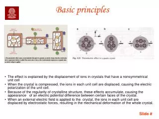
Types of sources Electro-magnetic - alternators, generators. Photo-electric ----- solar cells. Thermo-electric --- thermocouples Piezo-electric ------ gas lighters, microphones Chemical ---------- cells and batteries Static ---------------- lightning. 2.8.1.1 D
Component identification Resistive components:- all devices that have a principle function of producing heat. Inductive components:- any device that has a coil and principle operation uses magnetism. Capacitive components:- any device that stores an electro-static charge. 2.8.1.1 D
Resistance Resistance is the opposition to the flow of electrons. All materials exhibit a value of resistance to the flow of electrons. A good conductor has a small resistance, while an insulator has very high resistance. Resistance is a lot like friction; they both act to oppose motion and generate heat. 2.8.1.1 D
Component function Impedance AC resistance Reactance Resistance Urns Irons Inductance Heaters Capacitance Toasters Motors Relays Capacitors Transformers 2.8.1.1 D
Open Circuit An open circuit prevents current flow. A switch, fuse, or circuit breaker when operated will produce an open circuit. An open switch Open switch lamp is off. 2.8.1.1 E
Closed Circuit A closed circuit allows current to flow. A switch can control both open and closed circuits. Closed switch Closed switch lamp is on 2.8.1.1 E
Short Circuit This type of circuit is to be avoided whenever possible. The lamp is bypasses by a conductor connected directly across the supply and reducing the circuit resistance. High current flow Little current flow through the lamp, however excessive current flows in the short. The pressure of the circuit (volts) will also drop. Little current Short circuit 2.8.1.1 E
Ohms Law The current flowing in a circuit is proportional to the voltage and inversely proportional to the resistance of the circuit. V = Voltage I = Current R = Resistance V I R 2.8.1.1 E
Proportional to Proportional to , values that are directly opposite to each other in a formula is proportional to each other. Hexagon is proportional to the square. = Star is proportional to the circle. 2.8.1.1 E
Inversely proportional to Inversely proportional to, values that are diagonal to each other are inversely proportional to each other. This technique applies to all formularies. The star is inversely proportional to the square. = The hexagon is inversely proportional to the circle. 2.8.1.1 E
Triangle & thumb To transpose the formula, draw the triangle as shown. Voltage = ? Move thumb over voltage and the remainder equals the voltage. V I R 2.8.1.1 E
Triangle & thumb Voltage = current X resistance Determine the resistance. V I R 2.8.1.1 E
Triangle & thumb Thumb over the resistance. Resistance = the remainder. Resistance = voltage/current V I R 2.8.1.1 E
Transposing formula Current = voltage / resistance Resistance = voltage / current Voltage = current X resistance I = V R R = V I V=I R 2.8.1.1 E
Applying Ohms Law Determine the current flow. I=? V 10v 5 I R I = V = 10 = 2A R 5 2.8.1.1 F
Applying Ohms Law Determine the Resistance. I=5A V 100v R=? I R R = V = 100 = 20 I 5 2.8.1.1 F
Applying Ohms Law Determine the Voltage. I=12A V V=? 20 I R V=I R = 12 x 20 = 240v 2.8.1.1 F
Problem Solving Voltage Current Resistance I 50v 5A R V 16 240v 12 1A Calculate the missing value using ohms law. 2.8.1.1 F
Summary Ohms law is the relationship between voltage, current, and resistance. 50v 5A 10 16 240v 15A 12 1A 12v 2.8.1.1 F
Problems Determine the resistance of a 240v heating element that has a current of 20amps. A 240v light bulb, has a measured resistance of 960, determine the circuit current. A 240v element of 48 has been replaced by a 240v element with a resistance of 16. If the circuit is protected by an 8A circuit breaker, determine the effects on the circuit. 2.8.1.1 F
AS/NZS-3000:2007, Wiring Rules 3.7 ELECTRICAL CONNECTIONS 3.7.1 General Connections between conductors and between conductors and otherelectrical equipment shall provide electrical continuity andadequatemechanical strength. 2..8.1.1.G
Solderless lugs Ross - Courtney lug. Stanco lug 2..8.1.1.G
Crimps Terminating - crimp lugs. Joining cables of the same size - crimp links. When crimping it is important that the correct crimp type lug for the cable and the correct tool for that lug is used. AS/NSZ 3000 cl 3.7.2.3.2 2..8.1.1.G
Terminal connections AS/NZS 3000 cl 3.7.2.4 Blue point connectors (BP) Line taps. Articles terminals. Terminal strips. Bolted & clamp connectors, 2..8.1.1.G
AS/NZS-3000:2007 Wiring Rules 3.7.2.7 Soldered connections Where a soldered connection is used the design shall take account ofcreep, mechanical stress and temperature rise under fault conditions. 2..8.1.1.G
Stripping of Insulation. • Avoid using a knife on smaller cables. • Tear the insulation off, don’t cut. • Do not indent any conductor material. • Be sure not to remove excessive insulation. • Remake any damaged insulation. • The only connection for an extension lead is via an approved plugtop and socket. 2..8.1.1.G
AS/NZS-3000:2007 Wiring Rules 3.7.2.2 Preparation for connection The insulation on a conductor shall not be removed any further than isnecessary to make the connection. For connections between insulatedconductors the connection shall be insulated to provide a degree ofinsulation not inferior to that of the conductors. Any damaged insulationshall be reinstated. 2..8.1.1.G
Terminations and connections • Connections must not be soft soldered before compression terminations. • Must be seated correctly. • Free of dirt and oxides. • Use a suitable lug or connector. • Insulated to the equivalent of the original insulation. • Earth connection must be painted if exposed to weather 2..8.1.1.G
AS/NZS-3000:2007 Wiring Rules 3.7.2.6 Mechanical stress All cables and conductors shall be installed so that there is no unduemechanical stress on any connection. 2..8.1.1.G
AS/NZS-3000:2007 Wiring Rules 3.7.2.3.1 Loosening of connections Connections shall be made so that no loosening is likely because of vibration,alteration of materials or temperature variations towhich the connections are likely to be subjected in normal service. 2..8.1.1.G