Download
1 / 20
200 likes | 545 Views
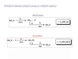
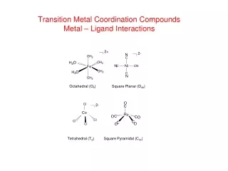
Metal-ligand s interactions in an octahedral environment. Six ligand orbitals of s symmetry approaching the metal ion along the x,y,z axes. We can build 6 group orbitals of s symmetry as before and work out the reducible representation. s.

E N D
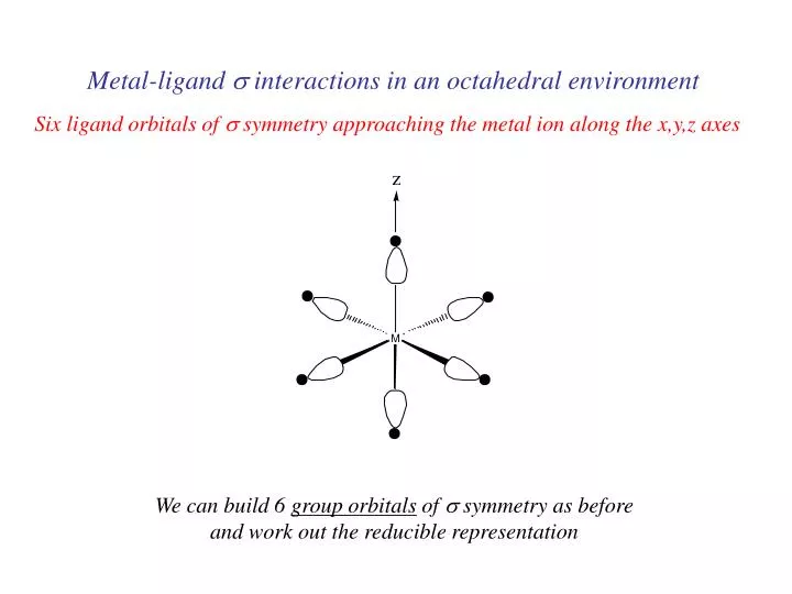
Metal-ligand s interactions in an octahedral environment Six ligand orbitals of s symmetry approaching the metal ion along the x,y,z axes We can build 6 group orbitals of s symmetry as before and work out the reducible representation
s If you are given G, you know by now how to get the irreducible representations G = A1g + T1u + Eg
anti bonding “metal character” non bonding 12 s bonding e “ligand character” “d0-d10 electrons” 6 s ligands x 2e each
Introducing π-bonding 2 orbitals of π-symmetry on each ligand We can build 12 group orbitals of π-symmetry
Gπ = T1g + T2g + T1u + T2u The T2g will interact with the metal d t2g orbitals. The ligand pi orbitals do not interact with the metal eg orbitals. We now look at things more closely.
Anti-bonding LUMO(π) First, the CN- ligand
Some schematic diagrams showing how p bonding occurs with a ligand having a d orbital (such as in P), or a p* orbital, or a vacant p orbital.
anti bonding “metal character” non bonding 12 s bonding e “ligand character” ML6s-only bonding “d0-d10 electrons” The bonding orbitals, essentially the ligand lone pairs, will not be worked with further. 6 s ligands x 2e each
Do Do has increased D’o Stabilization π-bonding may be introduced as a perturbation of the t2g/eg set: Case 1 (CN-, CO, C2H4) empty π-orbitals on the ligands ML π-bonding (π-back bonding) These are the SALC formed from the p orbitals of the ligands that can interac with the d on the metal. t2g (π*) t2g eg eg t2g t2g (π) ML6 s-only ML6 s + π (empty π-orbitals on ligands)
D’o Do has decreased Do Destabilization Stabilization π-bonding may be introduced as a perturbation of the t2g/eg set. Case 2 (Cl-, F-) filled π-orbitals on the ligands LM π-bonding eg eg t2g (π*) t2g t2g t2g (π) ML6 s-only ML6 s + π (filled π-orbitals)
Strong field / low spin Weak field / high spin Putting it all on one diagram.
Spectrochemical Series Purely s ligands: D: en > NH3 (order of proton basicity) • donating which decreases splitting and causes high spin: • D: H2O > F > RCO2 > OH > Cl > Br > I (also proton basicity) p accepting ligands increase splitting and may be low spin D: CO, CN-, > phenanthroline > NO2- > NCS-
Merging to get spectrochemical series CO, CN- > phen > en > NH3 > NCS- > H2O > F- > RCO2- > OH- > Cl- > Br- > I- Weak field, p donors small D high spin Strong field, p acceptors large D low spin s only
Turning to Square Planar Complexes Most convenient to use a local coordinate system on each ligand with y pointing in towards the metal. py to be used for s bonding. z being perpendicular to the molecular plane. pz to be used for p bonding perpendicular to the plane, p^. x lying in the molecular plane. px to be used for p bonding in the molecular plane, p|.
ML4 square planar complexes ligand group orbitals and matching metal orbitals s bonding p bonding (in) p bonding (perp)
Sample π- bonding ML4 square planar complexes MO diagram eg s-only bonding
Angular Overlap Method An attempt to systematize the interactions for all geometries. The various complexes may be fashioned out of the ligands above Linear: 1,6 Trigonal: 2,11,12 T-shape: 1,3,5 Square pyramid: 1,2,3,4,5 Octahedral: 1,2,3,4,5,6 Tetrahedral: 7,8,9,10 Square planar: 2,3,4,5 Trigonal bipyramid: 1,2,6,11,12
Cont’d All s interactions with the ligands are stabilizing to the ligands and destabilizing to the d orbitals. The interaction of a ligand with a d orbital depends on their orientation with respect to each other, estimated by their overlap which can be calculated. The total destabilization of a d orbital comes from all the interactions with the set of ligands. For any particular complex geometry we can obtain the overlaps of a particular d orbital with all the various ligands and thus the destabilization.
Thus, for example a dx2-y2 orbital is destabilized by (3/4 +6/16) es = 18/16 es in a trigonal bipyramid complex due to s interaction. The dxy, equivalent by symmetry, is destabilized by the same amount. The dz2 is destabililzed by 11/4 es.