Download
1 / 54
550 likes | 723 Views
AutoFocus - Case Tool. Mela Enrica. Summary. History AutoFocus as notation AutoFocus as tool Features. History. 1996

E N D
AutoFocus - Case Tool Mela Enrica
Summary • History • AutoFocus as notation • AutoFocus as tool • Features
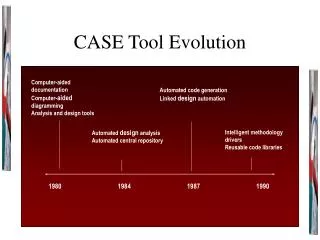
History • 1996 • The modeling tool has been built at the faculty of computer science at the Technische Universität München during the practical course `Software Engineering' by students and members of the chairs Prof. Broy and Prof. Endres • 1997 • A rapid prototyping and simulation environment implemented during the Softwaretechnik-Praktikum • 2000 … • Validas Ag has integrated many add-ons and free features into AutoFocus (code generation) • Based on the Validas tool infrastructure TUM build the prototype AutoFlex(next generation of AutoFocus)
Design tool AutoFocus • Embedded systems, which are logically (and later in the implementation possibly also physically) distributed • Uses a component-based paradigm to represent models of hierarchical structuring techniques, such as decomposition of system components during the development process • uses several graphical views • All system views have Based on the formal development method Focus
Summary • History • AutoFocus as notation • AutoFocus as tool • Features
Modeling with AutoFocus • Components : elements of the system which are physically or logically separated from each other • Ports: interfaces of components • Channels: connect two ports, are directed • Ports and channels are typed
Modeling with AutoFocus(2) • When modeling begins, the system as a whole is usually represented by just one single component (interface view of the system) • First, we have to determine which pieces of information enter and leave the system and in which form(input and output channels to the environment) • In the next step, we refine the structure. This means that subcomponents are identified, the tasks are allocated, and the channels between the subcomponents are specified. (architecture view) • The result is called decomposition • If necessary, individual components are decomposed further
Notation: System View • Structure view:System Structure diagrams(SSDs)for components, interfaces, and communication channels to model the structure of the system • Behaviour view:State transition diagrams(STDs)for the state-based description of the behaviour of components. • Interaction view: Extended event traces(EETs) for the interaction between components • Data view: Data type definitions(DTDs) allow to define the types of messages and data elements in a user-friendly, functional style
System Structure Diagrams • Describe the structure of a system with the aid of components, channels, and ports • Components communicate with each other via directed channels • Ports and channels are typed in order to determine which kind of data is sent through them. • A hierarchical description of the system is obtained by means of decomposing the components (sub-SSDs)
SSD: Decomposition • A component itself can be regarded as an independent system as well • By gradually decomposing a component into subcomponents, the structure of a system can be increasingly refined • Each decomposition is represented in a new SSD and is also called a refined view of the system
SSD Example: simple component name Exist decomposition type port Name type channel
Extended Event Trace • used to provide exemplary descriptions of the interaction of several components, either among each other or with their environment • Must be associated with : • a single component • To represent a typical input/output sequence of the associated component • a system structure diagram (SSD). • represents a typical interaction between the components of the system structure diagram and its environment (only channels, ports, and components should be used in the sequence diagram which exist in the associated system structure diagram)
EET(2) • vertical axis represent time axis which correspond to components in system structure diagrams (component lifelines) • Messages are represented by horizontal arrows between different axis (components) or between the environment • The order in which the messages in the sequence diagram are represented from top to bottom indicates the time sequence of the events • Events may also occur simultaneously • Explicit time steps are represented by horizontal broken lines. Event separated by time step definitely occur one after the other • Loop (indicator) may be annotated to determine the number of the runs
EET: Structuring Elements • offer possibilities of structuring interaction scenarios hierarchically • so-called boxes can be used, in which a set of sub-EETs can be named • Since any of the sub-EETs can be chosen as interaction for the period in question, boxes offer the possibility of structuring as well as of introducing behavior variations in EETs
EET: Structuring Structuring view exist structuring interaction scenarios
EET: refinement • Another option for hierarchical description • Analogously to the decomposition in the associated SSD • In order to ensure consistency, all inputs/outputs of the super-EET must appear in the redefined view
EET: refinement Refinement view exist indicator
State Transition Diagrams • describe the behaviour of a system or a component in terms of its reactions to inputs from the environment and the resulting outputs to the environment • The reactions depend on the current state of the component • Association describe as a state control move into another state control • Data State is represented by internal parameters and external parameters (ports) of the component
Local Variables • Each system component may have (any number of) local variables • declared with the respective component in the system structure (SSD) • Only the state transition system associated with the component can access the local variables • have a name and an assigned type
Association • connect two control states: the source state and the target state. • the source state need not necessarily differ from the target state. • can be described more precisely with the following attributes: • Label • Comment Precondition:input:output:postcondition
input output STD: Example
State Transition Diagrams(STD )Example Label Wait in yellow (t>0):::t=(t-1)
Data Type Definitions • AutoFocus used typed languages • This applies, fir instance, to every channel name and every port name • There are also formulas and patterns and they also have types
DTD(2) • AutoFocus supports two approaches: • Java: a partial set of the basic types of the java programming language can be used for typing • It is not possible to use self-defined types • QuestF: is a functional programming language • The basic type of QuestF and the type introduced with the data construct can be used for typing • In a project, it is not possible to mix the two approaches
DTD: Example • Data TrafColor = red | RedYellow | green | yellow; • Set a type TrafColor with four different constants (red, RedYellow, green and yellow) • Data PedColor = walk | stop; • A type PedColor with the two constants walk and stop. • data Datum = TMJ(tag:Int, monat:Int, jahr:Int); • Constructors may also have parameters.
Summary • History • AutoFocus as notation • AutoFocus as tool • Features
AutoFocus: Tool • Project browser • Editors • Consistency Assurance • Simulation • Code generation
User Interface • Consists of • a project browser for the organization of the specification documents of the single project, • one editor for each kind of specification document
Consistency Assurance • The information describing the system as a whole is spread over several views and layers of abstraction. This is a major source of errors and inconsistencies • uses different as well as hierarchically organized views, it is important to ensure that the information spread over the various views is well-defined or "consistent" in a methodological sense
The Consistency Notion • Grammatical correctness • the syntactic rules for the textual representation and the graph- grammatical rules for the graphical representation are observed in the various views • Interface correctness • if one view is hierarchically embedded into another view, the views must have compatible interfaces • Definedness • if elements from one view are used in another view, they must be defined in the respective view • Type correctness • the type required for using an element must correspond to the element type • Completeness: all "essential" views of a project are available • Only static consistency
The Consistency Notion • Several consistency conditions are already integrated • The consistency check is started in the project browser • The tool then carries out the selected checks and afterwards shows the list of all inconsistencies found, together with the affected views • The type correctness of terms can only be verified in DTDs. If transitions are not type correct, however, this may cause errors during simulation as well
Simulation • It is possible to simulate the behavior of any component whose behavior was previously laid down in a STD or which was split up into subcomponents. • consists of animations of the SSDs, the STDs, and the EET displays which correspond to the respective run of the system • It is absolutely essential to perform a consistency check before the first simulation.
Features : Code Generation • Validas AG has integrated many add-ons and free features: • C code generation • Java code generator