Download
1 / 57
630 likes | 1.01k Views
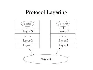
Ultra-Wideband (UWB 2): Physical Layer Options and Receiver Structures. Fundamentals Fundamentals of short/medium range wireless communication 1 digital transmission systems equivalent baseband model digital modulation and ML-detection

E N D
Ultra-Wideband (UWB 2): Physical Layer Options and Receiver Structures
Fundamentals Fundamentals of short/medium range wireless communication 1 digital transmission systems equivalent baseband model digital modulation and ML-detection Fundamentals of short/medium range wireless communication 2 fading channels diversity MIMO wireless Fundamentals of short/medium range wireless communication 3 Multicarrier modulation and OFDM Systems I: OFDM based broadband access WLAN 1: IEEE 802.11g, a WLAN 2: IEEE 802.11n WMAN: (mobile) WiMAX Vehicular Networks Systems II: Wireless short range access technolgies and systems UWB 1: Promises and challenges of Ultra Wideband Systems UWB 2: Physical Layer options Wireless Body Area Network case study: UWB based human motion tracking The IEEE 802.15x family of Wireless Personal Area Networks (WPAN): Bluetooth, ZigBee, UWB Systems III: RF identification (RFID) and sensor networks RFID 1 RFID 2 Outline of Course Communication Technology Laboratory Wireless Communication Group
Outline • Physical Layer Options • UWB Impulse Radio • Direct Sequence UWB • UWB Multiband • Receiver Structures • RAKE Receiver • Transmitted Reference Receiver • Energy Detector • Appendix • IEEE 802.15.3a Multipath Model
Ultra-Wideband Impulse Radio (UWB-IR)
UWB-IR: Modulation and MA Options • Modulation schemes: PPM, BPSK (BPAM), PAM, OOK, PSM, … • MA schemes: TH-MA, DS-MA, PS-MA, RD-MA, …
One receiver One transmitter Peer-to-Peer Scenario: • In the following, we discuss UWB-IR modulation schemes in peer-to-peer communication: • Only one transmitter and one receiver • No interferer • No need for a MA scheme. Picture from [Weisenhorn, IZS, 2004]
Similarities Among UWB-IR Systems: • Application of very short duration pulses with , occupying a very large bandwidth of . • In contrast to UWB-MB, the whole band is used in one block. • Each symbol consists of pulses Repetition coding • One pulse per frame ( ) • Very low duty cycle Time
Symbol ‘-1’ Time Symbol ‘1’ Most Popular UWB-IR Modulations: Binary Pulse Amplitude Modulation (BPAM) (Binary Phase Shift Keying (BPSK)) Binary Pulse Position Modulation (BPPM) Symbol ‘1’ Symbol ‘0’ Time and and • Modulation of pulse position • Extension to any M-ary PPM possible with: • Modulation of pulse polarity Pictures from [Giannakis, CEWIT, 2003]
Symbol ‘1’ Time Symbol ‘2’ Other Types of PAM: Pulse Amplitude Modulation (PAM) On-Off Keying (OOK) Symbol ‘0’ Time Symbol ‘1’ and and • Modulation of amplitude • Extension to any M-ary PAM possible Pictures from [Giannakis, CEWIT, 2003]
s(t) t Tf Example of BPPM: g(t) • transmitting Ts s(t) d • transmitting t Tf Ts
Example of BPAM: g(t) s(t) • transmitting t Tf Ts s(t) • transmitting t Tf Ts
Uncoordinated Multiple Access Scenario: • Multiple access (MA) scheme required to reduce interference! [Weisenhorn, IZS, 2004]
* Direct Sequence Spread Spectrum (DSSS): Conventional Principle DSSS signal Data signal „Chip“ sequence Time domain Frequency domain Data signal convolution Pseudo-Random sequence Spread data signal
* Direct Sequence in UWB-IR (1): DS data signal „Chip“ sequence Data signal Spectral Lines due to Rep. Coding Time domain Frequency domain Data signal Pseudo-Random sequence Randomized data signal
Direct Sequence in UWB-IR (2): User A specific binary pseudo-random sequence (PN) of length User B specific binary pseudo-random sequence (PN) of length User A User B ... ... Time Pictures from [Giannakis, CEWIT, 2003]
DS-UWB Compared to DSSS: • DS in UWB-IR is very similar to DSSS in conventional systems: • Data bit is spread over multiple consecutive pulses. • Pseudo-random code is used to separate users (MA). • Spectrum is smoothed very efficiently. but: • In UWB-IR-DS the code rate equals the pulse rate. • Spectrum is not significantly spread by the DS.
User A specific 5-ary pseudo-random sequence (PN) of length User B specific 5-ary pseudo-random sequence (PN) of length Time-Hopping Multiple Access: User A User B ... ... Time Pictures from [Giannakis, CEWIT, 2003]
Time-Hopping Properties: • Data bit is spread over multiple consecutive pulses. • Pseudo-random code is used to separate users (MA). • User separation also possible in non-coherent receivers such as the energy detector. • Spectral smoothening not as effective as with DS.
Outline • Matched filter • Receiver structures • Rake • Transmitted reference • Energy detector 20
Introduction • Pulse based UWB • Transmitter and receiver for UWB are said to be very simple due to no need of Mixers, RF Oscillators and PLLs • For transmitters this assumption holds probably • But receivers are probably more complex as often assumed since energy has to be captured from all multipaths 21
Matched Filter • Transmission of a single pulse s(t) with duration T • n(t) is a white Gaussian noise process of zero mean and power spectral density N0/2 • Receiver consists of a linear time-invariant filter g(t) and a sampler single pulse receiver The matched filter g(t) = s(-t+T) is a time reversed and delayed version of the input signal s(t). It maximizes the SNR at the sampling instant T. 22
UWB System with Multipath Channel TX RX 23
Matched Filter for Multipath Channel I • Optimum receiver: correlator or matched filter + 24
Matched Filter for Multipath Channel II + + correlator in each branch „RAKE“ 25
ARAKE (All RAKE) • Optimum receiver with unlimited resources • Combines all N resolved multipath components • Number of resolvable components N increases with bandwidth => large number of RAKE fingers 26
SRAKE (selective RAKE) • Also referred as selection combining (SC) • Only subset of resolved multipath components is processed • Selects the L strongest paths • Better performance than a single path receiver • Requires the knowledge of the instantaneous values of all multipath components L = 6 27
Impact on the design of WBAN´s Number of RAKE fingers using a SRAKE • Antennas placed on the front side of the body in 15cm steps • Collecting 75% of the whole energy (front side measurements) • 2 fingers @ 15cm • 20 fingers @ 90cm Short distance multihop increases the energy that can be captured with a simple RAKE 28
PRAKE (Partial RAKE) • Sometimes also referred as nonselective combining (NSC) • Collects the energy from the M first multipath components • These multipath components must not be the best, e.g. in NLOS environment • Compared to SRAKE no selection mechanism is required • Needs only to find the first M multipath components => complexity reduction M = 6 29
Selective nonselective Combining (SC-NSC) • Only the strongest path is tracked • The K-1 paths following the strongest path are chosen for the remaining path delays • SC-NSC is better suited for NLOS channels (where the direct path with the shortest delay, i.e. the first path, is attenuated) than PRAKE/NSC since the strongest path can be tracked K = 6 30
Conclusions on Rake Receivers • ARAKE is an optimum receiver • Realization of a matched filter • High complexity • Complexity reduction by using only a fraction of all paths • Performance degradation • Channel estimation necessary • Amplitudes and delays have to be known • Simpler receiver structures without channel estimation would be desirable 31
Principles of Transmitted Reference Systems • 2 pulses (=1 doublet) are transmitted for one symbol • 1st pulse is the reference pulse, which is used as template • 2nd pulse is the data pulse • Implicit channel estimation since both pulses pass the same channel • Channel has to be invariant over 1 doublet only • BPF required for noise reduction • Noisy template for correlation • Information rate usually drops by 50 % since half of the pulses are used as reference 33
TR PAM I • Information in the amplitude of the data pulse Reference pulses Data pulses 34
TR PAM II • TX energy higher since two pulses are needed for 1 bit • Correlation of reference and data pulse BPF • Performance depends on the time of integration Tp • Performance degradation if inter-pulse interference existing 35
Integration Duration I • BER performance depends on the integration duration • If integration duration is too short, not enough energy can be captured • If integration duration is too long, the CIR is decayed so much that the noise term gets dominant • Channel models from IEEE 802.15.3a • LOS (Line of Sight) • NLOS (Non-Line of Sight) LOS NLOS 36
Integration Duration II • Body area network measurements around the torso • In general, shorter integration duration for LOS links than for NLOS 37
Energy Detector I • Energy detector (ED) collects energy from multipaths • Integrates the energy of the receive signal • Non-coherent receiver structure • No antipodal signaling possible, e.g. BPSK • Usually used with pulse position modulation (PPM) • No explicit channel estimation is necessary • Begin and end of the integration interval has to be known 39
Energy Detector II Pulse Position Modulation (2 PPM) BPF • Integration of noise on the position where no pulse is located 40
Performance Comparison • Real measured channels around the human body (15cm distance quasi LOS) • Performance of TR and ED similar but about 6 dB worse than MF 41
Conclusions • TR and ED are much simpler than an ARAKE • No explicit channel estimation necessary • Position of the receive signal in time domain has to be known accurate • Performance is worse than ARAKE • Performance strongly depends on integration duration • Integration duration is for LOS channels usually shorter than for NLOS channels 42
Appendices UWB Multiband (Certified Wireless USB IEEE 802.15.3a Multipath Model
Ultra-Wideband Multi-Band (UWB-MB)
UWB-Multiband OFDM • Spectrum is divided into sub-bands • Serial transmission over the sub-bands • Application of TF codes for piconet separation • Strongly promoted by industry (Wireless USB, WiMedia, MBOA)
ECMA-368 (MB-OFDM Standard): Basic Idea • Split overall spectrum into 14 bands of 524MHz bandwidth • Serial transmission of OFDM symbols over the bands • OFDM symbol: • 128 point FFT/IFFT independent of data rate • Modulation: QPSK or DCM • Information is coded across several bands (TF codes) to achieve frequency diversity and piconet separation. • Zero-padded suffix: • Robustness against multi-path • Time to switch band
Overall band of 7.5GHz is split into14 bands: Bandwidth: 524MHz Separation: 524MHz Bands are grouped into 5 band groups Several TF codes for each band group several piconets Band groups are managed by FDMA: Better SOP performance ECMA-368: Bandplan [ECMA-386, 2006]
Code Map of Band Group 1: Fixed Frequency Interleaved Channels (FFI) Time Frequency Interleaved Channels (TFI) [ECMA-386, 2006]
EMCA-368: Rate Independent Parameters • 8 OFDM tones are set to zero. [ECMA-386, 2006]
ECMA-368: Rate Dependent Paramters [ECMA-386, 2006]