Download
1 / 7
70 likes | 157 Views
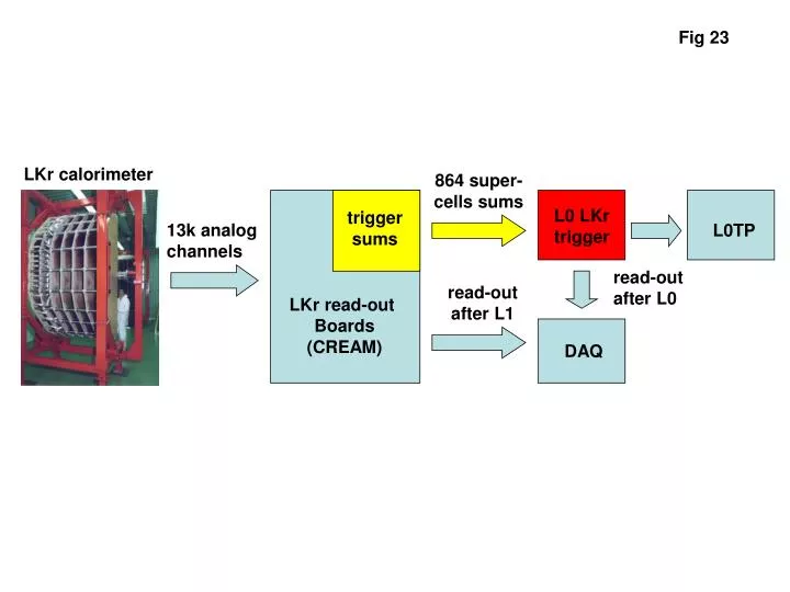
Fig 23. LKr calorimeter. 864 super- cells sums. L0 LKr trigger. trigger sums. 13k analog channels. L0TP. read-out after L0. read-out after L1. LKr read-out Boards (CREAM). DAQ. Fig 24. Concentrator. Front-End. Concentrator. 32 trigger tiles. 8 ch. 32 ch. 8 ch. TEL62.

E N D
Fig 23 LKr calorimeter 864 super- cells sums L0 LKr trigger trigger sums 13k analog channels L0TP read-out after L0 read-out after L1 LKr read-out Boards (CREAM) DAQ
Fig 24 Concentrator Front-End Concentrator 32 trigger tiles 8 ch 32 ch 8 ch TEL62 TEL62 TEL62 1-3 m copper 1-3 m copper GbE LKr RX LKr RX LKr Interface QuadGbE Trigger& RO TX Trigger& RO TX L0TP GbE GbE DAQ GbE
Fig 25 Concentrator board: merging, sorting 8 front-end board 1 trigger tile = 2x8 channels Front-end board: pulse reconstruction (time, position and energy) 32 trigger tiles (1 tile = 2x8 liquid krypton cells)
Fig 26 Peak in space Peak finder (one channel) Peak in time Over threshold Peak processor(one channel) Parabolic fit 7 bit reconstructed fine time
Fig 27 Maximum in the red area: cluster handled by the “red” concentrator Maximum in the blue area: cluster handled by the “blue” concentrator For clusters at the boundary between two FE TEL62s the peak is reconstructed in the concentrator
Fig 28 a ( 30 MHz / 28 ) x 3 / 8 = 0.4 ( 30 MHz / 28 ) x 3 = 3.2 ( 30 MHz / 28 ) x 3 = 3.2 TOTAL RATE = 10 MHz
Fig 28 b ( 30 MHz / 28 ) x 3 / 8 = 0.4 ( 30 MHz / 28 ) x 3 / 4 = 0.8 ( 30 MHz / 28 ) x 3 /4 = 0.8 TOTAL RATE = 4.8 MHz