Download
1 / 11
110 likes | 205 Views
Inboard Diverter Tile Concepts Comparison. Design Baseline with crossing T-Bars Single Larger T-Bar Single Larger T-Bar Split and Pinned (ala TFTR) Three Point Rotating Supports Smaller Tiles – 7.5 vs 15 deg – with Single Larger T-Bar

E N D
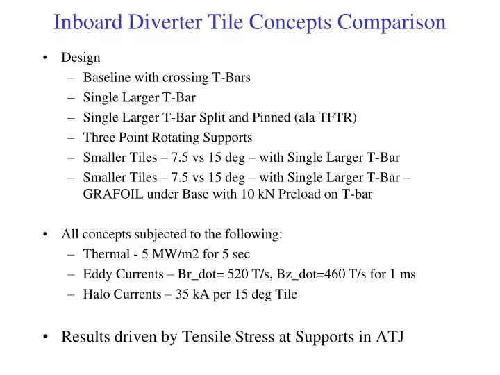
Inboard Diverter Tile Concepts Comparison • Design • Baseline with crossing T-Bars • Single Larger T-Bar • Single Larger T-Bar Split and Pinned (ala TFTR) • Three Point Rotating Supports • Smaller Tiles – 7.5 vs 15 deg – with Single Larger T-Bar • Smaller Tiles – 7.5 vs 15 deg – with Single Larger T-Bar – GRAFOIL under Base with 10 kN Preload on T-bar • All concepts subjected to the following: • Thermal - 5 MW/m2 for 5 sec • Eddy Currents – Br_dot= 520 T/s, Bz_dot=460 T/s for 1 ms • Halo Currents – 35 kA per 15 deg Tile • Results driven by Tensile Stress at Supports in ATJ
Baseline Ibdhs102810/Ibdhs001_struct
Larger T-Bar Ibdhs112410/Ibdhs009_structx
Split and Pinned T-Bar Ibdhs011011/Ibdhs804_struct
Three point pivoting supports Ibdhs010511/Ibdhs703_struct
Pivoting Supports Details Bolt T-Bar Spherical Washers Retaining Clips Not to scale
Smaller 7.5deg Tile Ibdhs120810/Ibdhs101_struct19 Ibdhs120810/Ibdhs101_struct
Grafoil under base of Tile and T-bar T-bar Preloaded to 10 kN Preload only much lower Smaller 7.5deg Tile Ibdhs120810/Ibdhs101_struct21
Summary *Single T-Bar Concepts need to provide radial constraint not explicitly modeled
Conclusions • Baseline with crossing T-Bars • T-slot to small to carry launching force and over turning moments from EM loads. Over constrains tile from thermal load • Single Larger T-Bar • Show improvement over baseline (above) but still over constrains tile from thermal along T-bar axis • Single Larger T-Bar Split and Pinned (ala TFTR) • Attempt to relieve thermal stress along axis – While flexible for thermal, unable to distribute launching load • Three Point Rotating Supports • Allows fairly free thermal expansion. Stress dominated by EM launching forces • Smaller Tiles – 7.5 vs 15 deg – with Single Larger T-Bar • Significant reduction compared to larger tile with Single Larger T-Bar • Gain in thermal stress for smaller tile less than expected due Tile/Tbar relative stiffness • Smaller Tiles – 7.5 vs 15 deg – with Single Larger T-Bar – GRAFOIL under Base with 10 kN Preload on T-bar • Reduces impact of EM loads (ie behaves like preloaded joint) but increases constraint from thermal load
Conclusions • Recommend design that shows better performance for thermal loads, while still performing adequately with EM loads • Thermal loads are more predictable. Better thermal margin may allow for higher heat fluxes if EM loads prove to be less severe • EM loads are less certain and analysis has assumed the worse