Download
1 / 26
350 likes | 687 Views
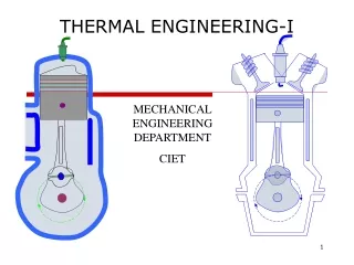
THERMAL ENGINEERING (ME 2301 ). M.R.SWAMINATHAN Assistant Professor Department of Mechanical Engineering Anna University Chennai Chennai-25. SYLLABUS. Unit-I – Air Standard Cycles, Valve Timing Unit-II – IC Engines Unit-III - Steam Turbines & Nozzles Unit-IV - Air Compressors

E N D
THERMAL ENGINEERING(ME 2301 ) M.R.SWAMINATHAN Assistant Professor Department of Mechanical Engineering Anna University Chennai Chennai-25
SYLLABUS • Unit-I – Air Standard Cycles, Valve Timing • Unit-II – IC Engines • Unit-III - Steam Turbines & Nozzles • Unit-IV - Air Compressors • Unit-V - Refrigeration & Air-Conditioning
AIR STANDARD CYCLES • The working fluid is air, which continuously circulates in a loop and always behaves as an ideal gas. • All the processes that make up the cycle are internally reversible. • The combustion process is replaced by a heat-addition process from an external source. • The exhaust process is replaced by a heat rejection process that restores the working fluid to its initial state.
Another assumption utilised to simplify the analysis even more is that the air has constant specific heats whose values are determined at room temperature (25°C, or 77°F). • Assumptions are called the cold-air-standard assumptions. • A cycle for which the air-standard assumptions are applicable is frequently referred to as an air-standard cycle
COMPRESSION RATIO The ratio of the maximum volume formed in the cylinder to the minimum (clearance) volume is called the compression ratio of the engine.
The compression ratio is a volume ratio and should not be confused with the pressure ratio. Mean effective pressure (MEP) is a fictitious pressure that, if it acted on the piston during the entire power stroke, would produce the same amount of net work as that produced during the actual cycle.
CARNOT CYCLE • The Carnot cycle is composed of totally four reversible processes: • isothermal heat addition, • isentropic expansion, • isothermal heat rejection • isentropic compression
CARNOT CYCLE The Carnot cycle can be executed in a closed system (a piston-cylinder device)and either a gas or vapor can be used as the working fluid.
Otto Cycle: The ideal Cycle for Spark-Ignition Engines Figures below show the actual and ideal cycles in spark-ignition (SI) engines and their P- diagrams.
Ideal Otto Cycle The thermodynamic analysis of the actual four-stroke or two-stroke cycles can be simplified significantly if the air-standard assumptions are utilized. The T-s diagram of the Otto cycle is given in the figure at left.
The ideal Otto cycle consists of four internally reversible processes: 12 Isentropic compression 23 Constant volume heat addition 34 Isentropic expansion 41 Constant volume heat rejection
Thermal Efficiency of an Otto Cycle The Otto cycle is executed in a closed system, and disregarding the changes in kinetic and potential energies, we have
Engine Knock and Thermal Efficiency The thermal efficiency of the ideal Otto cycle increases with both the compression ratio and the specific heat ratio.
When high compression ratios are used, the temperature of the air-fuel mixture rises above the auto-ignition temperature produces an audible noise, which is called engine knock. (antiknock, tetraethyl lead? unleaded gas) • For a given compression ratio, an ideal Otto cycle using a monatomic gas (such as argon or helium, γ = 1.667) as the working fluid will have the highest thermal efficiency.
DIESEL CYCLE The diesel cycle is the ideal cycle for CI (Compression-Ignition) reciprocating engines. The CI engine first proposed by Rudolph Diesel in the 1890s, is very similar to the SI engine, differing mainly in the method of initiating combustion.
In diesel engines, ONLY air is compressed during the compression stroke, eliminating the possibility of auto-ignition. Diesel engines can be designed to operate at much higher compression ratios, typically between 12 and 24.
The fuel injection process in diesel engines starts when the piston approaches TDC and continues during the first part of the power stroke. Therefore, the combustion process in these engines takes place over a longer interval.
Because of this longer duration, the combustion process in the ideal Diesel cycle is approximated as a constant-pressure heat-addition process. This is the ONLY process where the Otto and the Diesel cycles differ.
Thermal efficiency of Ideal Diesel Cycle Under the cold-air-standard assumptions, the efficiency of a Diesel cycle differs from the efficiency of Otto cycle by the quantity in the brackets.
The quantity in the brackets is always greater than 1. Therefore, hth,Otto > hth, Dieselwhen both cycles operate on the same compression ratio. Also the cuttoff ratio, rc decreases, the efficiency of the Diesel cycle increases.
BRAYTON CYCLE – GAS TURBINE The open gas-turbine cycle can be modeled as a closed cycle, as shown in the figure below, by utilizing the air-standard assumptions
BRAYTON CYCLE - PROCESSES 12 Isentropic compression (in a compressor) 23 Constant pressure heat addition 34 Isentropic expansion (in a turbine) 41 Constant pressure heat rejection
The highest temperature in the cycle occurs at the end of the combustion process, and it is limited by the maximum temperature that the turbine blades can withstand.