Download
1 / 46
510 likes | 1k Views
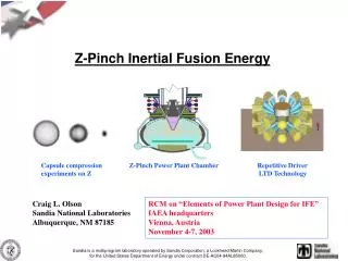
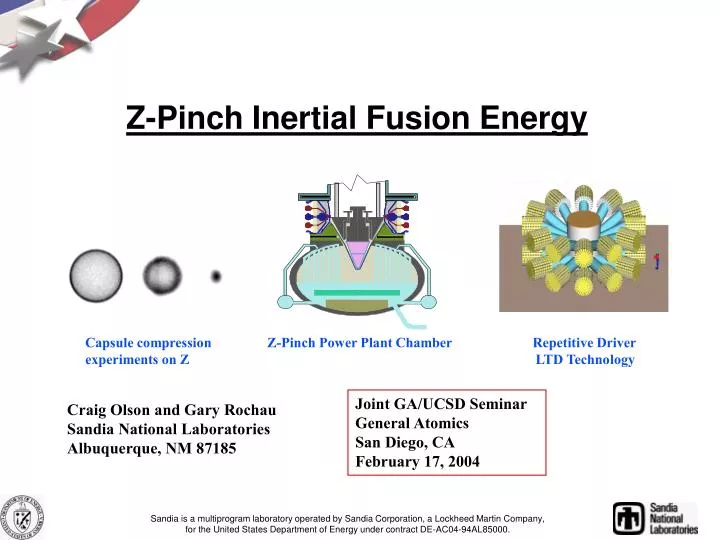
Z-Pinch Inertial Fusion Energy . Capsule compression Z-Pinch Power Plant Chamber Repetitive Driver experiments on Z LTD Technology.

E N D
Z-Pinch Inertial Fusion Energy Capsule compression Z-Pinch Power Plant Chamber Repetitive Driver experiments on Z LTD Technology Joint GA/UCSD Seminar General Atomics San Diego, CA February 17, 2004 Craig Olson and Gary Rochau Sandia National Laboratories Albuquerque, NM 87185 Sandia is a multiprogram laboratory operated by Sandia Corporation, a Lockheed Martin Company,for the United States Department of Energy under contract DE-AC04-94AL85000.
Part 1 Z-Pinch Inertial Fusion Energy
Z-Pinch IFE Team (1000 and 6000, plus Universities &Industry) C. L. Olson,a G. E. Rochau,a S. A. Slutz,a C. W. Morrow,a G. A. Rochau,a R. E. Olson,a A. R. Parker,a M. E. Cuneo,a D. L. Hanson,a G. R. Bennett,a T. W. L. Sanford,a G. A. Chandler,a J. E. Bailey,a W. A. Stygar,a J. L. Porter,aR. A. Vesey,a T. A. Mehlhorn,a K. W. Struve,a M. G. Mazarakis,aL. X. Schneider,a K. R. Prestwich,a G. Benevides,a T. J. Renk,a T. J. Tanaka,a M. A. Ulrickson,a D. H. McDaniel,a M. K. Matzen,a J. P. Quintenz,aP. F. Peterson,bJ. S. De Groot,c R. R. Peterson,d,e D. Kammer,e I. Golovkin,e G. L. Kulcinski,e E. Mogahed,e I. Sviatoslavsky,e M. Sawan,e C. Gibson,fH. Tran,g P. Panchukh, R. Lumiai aSandia National Laboratories, Albuquerque, NM bUniversity of California, Berkeley, CA cUniversity of California, Davis, CA dLos Alamos National Laboratory, Los Alamos, NM eUniversity of Wisconsin, Madison, WI fGeneral Atomics, San Diego, CA gUniversity of New Mexico, Albuquerque, NM hEG&G, Albuquerque, NM iInControl, Inc., Albuquerque, NM US/Russia collaboration on Z-Pinch IFE -
The long-range goal of Z-Pinch IFE is to produce an economically-attractive power plant using high-yield z-pinch-driven targets (3 GJ) at low rep-rate (0.1 Hz) Z-Pinch IFE DEMO (ZP-3, the first study) used 12 chambers, each with 3 GJ at 0.1 Hz, to produce 1000 MWe
2038 2024 2018 2012 2008 2004 1999 Z-Pinch IFE Road Map Z-Pinch IFE DEMO Z-Pinch ETF (ETF Phase 2) $1B Laser indirect-drive Ignition Z-Pinch High Yield Z-Pinch Ignition High Yield Facility (ETF Phase 1) Z-Pinch IRE $150M (TPC) +op/year Z-Pinch IFE target design $5M /year Z-Pinch IFE target fab., power plant technologies $5M /year FI ZR Z Z-Pinch IFE PoP $10M /year Z-Pinch IFE target design $2M /year Z-Pinch IFE target fab., power plant technologies $2M /year Z-Pinch IFE CE $400k /year (SNL LDRD +) NIF Year Single-shot, NNSA/DP Repetitive for IFE, OFES/VOIFE
Driver pulsed power: _________ Marx generator/ magnetic switching linear transformer driver water line technology (RHEPP technology) (LTD technology) Power feed: ____ triax coax RTL: ____ Flibe/electrical coating Flibe immiscible material (e. g., low activation ferritic steel) Target: __ double-pinch dynamic hohlraumfast ignition Chamber: _ dry-wall wetted-wall thick-liquid wall solid/voids Z-Pinch IFE Matrix of Possibilities (choose one from each category) Z-Pinch Driver: ______________ Marx generator/ magnetic switching linear transformer driver water line technology (RHEPP technology) (LTD technology) RTL (Recyclable Transmission Line): _____ Flibe/electrical coating immiscible material (e. g., low activation ferritic steel) Target: _ double-pinch dynamic hohlraumfast ignition Chamber: ____ dry-wall wetted-wall thick-liquid wall solid/voids (e. g., Flibe foam) Mainly science: z-pinch target physics Mainly engineering/technology: z-pinch driver, RTL, chamber
Z-pinches offer the promise of a cost-effective energy-rich source of x-rays for IFE High Yield Facility ZR Z Saturn Proto II Supermite ZR will be within a factor of 2-3 in current (4-9 in energy) of a High Yield driver.
(all are 60 MA) ( 90 MA) ( 60 MA) (28 MA) (18 MA) (10 MA) (10 MA) (1 MA)
Time (s) Marx generator/ water line driver technology is used on Saturn and Z/ZR x rays ~1.8 MJ Z Modular High Efficiency ( 15% wall-plug to x-rays) Low cost ( $30/J) Laser-triggered pressurized gas switches Technology is possibly rep-rateable at 0.1 Hz with fast-cycling Marx vacuum water Marx 11.4 MJ
RHEPP II has demonstrated the high average power capabilities of magnetic switching 420 kW, 2.7 kJ/pulse, 220 kV Blumlein PFL Modular High Efficiency ( 50 % for driver) Low Cost Magnetic switches (~ unlimited lifetime) Already demonstrated at 120 Hz (overkill for Z- Pinch IFE) 2.2 MeV, 25 kA, 120 Hz, 300 kW
Linear Transformer Driver (LTD) technology is compact and easily rep-rateable • LTD uses parallel-charged capacitors in a cylindrical geometry, with close multiple triggered switches, to directly drive inductive gaps for an inductive voltage adder driver (Hermes III is a 20 MV inductive voltage adder accelerator at SNL) • LTD requires no oil tanks or water tanks • LTD study (as shown) would produce 10 MA in about 1/4 the size of Saturn • LTD pioneered in Tomsk, Russia Modular High Efficiency (~ 90% for driver) Low Cost Switches: ball-gaps in air, pressurized gas, solid-state Easily rep-rateable for 0.1 Hz
Key Z-Pinch Driver Issues • Selecting best option (Marx/water line/ RHEPP/ LTD) • Long-lifetime switches • Power flow configuration (from wall-plug to RTL) All approaches are robust, industrial quality, modular, high efficiency, pulsed power drivers
RTL (Recyclable Transmission Line)
Z-pinch power plant chamber uses an RTL (Recyclable Transmission Line) to provide the standoff between the driver and the target INSULATOR STACK (connects to driver) RTL FLIBE JETS Z-PINCH TARGET 10-20 Torr Inert Gas Yield and Rep-Rate: few GJ every 3-10 seconds per chamber (0.1 Hz - 0.3 Hz) Thick liquid wall chamber: only one opening (at top) for driver; nominal pressure (10-20 Torr) RTL entrance hole is only 1% of the chamber surface area (for R = 5 m, r = 1 m) Flibe absorbs neutron energy, breeds tritium, shields structural wall from neutrons Eliminates problems of final optic, pointing and tracking N beams, high speed target injection Requires development of RTL
Recyclable Transmission Line (RTL) status/issues RTL movement (“automobile assembly line technology”) RTL electrical turn-on RTL low-mass limit and electrical conductivity RTL structural properties/ chamber pressure RTL mass handling RTL shrapnel formation RTL vacuum connections/ electrical connections RTL activation/ waste stream analysis RTL shock disruption to fluid walls RTL manufacturing/ cost RTL optimum configuration (coax, triax, convolute, shape, inductance, material, mass) RTL power flow limits (physics of magnetic insulation) Effects of post-shot EMP, plasma, droplets, debris up the RTL Shielding of sensitive accelerator/power flow feed parts ...
RTL replacement requires only modest acceleration for IFE L = 0.5 a t2 , or a ~ 1/t2 Acceleration is 104 less than for IFE target injection for ions or lasers 104 g 1 g 10 g 0.1 g 100 g 1,000 g rifle bullet 0.01 g IFE RTL replacement for rep-rated z pinches Prometheus-L OSIRIS, SOMBRERO, Prometheus-H Car (0 - 60 mph in 10 s) IFE target injection for ions and lasers (~ 10 Hz) (~ 0.1 Hz)
RTL electrical turn-on RTL experiments on Saturn at the 10 MA level show uniform electrical turn-on for all materials tested Height: 30 cm Diameter: 8 cm Gap: 3 mm • The diameter of the RTL was chosen to provide current density comparable to a reactor system • Power flow within Saturn limits the load inductance to less than 5 nH. • Only nontoxic materials were tested, e. g. tin, aluminum, and stainless steel • Current monitors placed at the top, middle, and bottom of the RTL showed no loss of current for any material
RTL Structural RTL FINITE ELEMENT MODEL constructed in ANSYS to perform structural analysis R = 50 cm r = 5 cm L = 200 cm 25 mil steel disc 10 cm lip Fusion Technology Institute University of Wisconsin, Madison
RTL Structural PRELIMINARY BUCKLING ANALYSIS of steel RTL 78 Torr RTL buckles at 1.52 psi = 78 Torr as shown 20 Torr no effect (safe operating point) Fusion Technology Institute University of Wisconsin, Madison
RTL mass handling One day storage supply of RTLs (at 50 kg each) has a mass comparable to one day’s waste from a coal plant Z-Pinch IFECoal-fired Power Plant (1 GWe Power Plant) San Juan Generating Station (1.6 GWe) (Four Corners area, NM) Burns: 7 million tons coal/year Waste: 1.5 million tons/year RTLs one-day storage Coal 30-day storage supply supply at site is 5,000 tons at site is 600,000 tons Burns: 20,000 tons/day Waste: 5,000 tons/day (flyash and gypsum, that must be disposed of in the adjacent coal mine) RTLs are recycled with minimum waste
Target+RTL interaction with liquid wall Capability to model thick liquid wall disruption by the target explosion may be studied using chemical detonations with liquid flows Impulse-affected region- note divot “New” liquid interface 25 cm 10 msec 2 msec 18 msec 26 msec - 6 msec . 4 0 I = 45 Pa sec 3 0 Surface position (mm) 2 0 1 0 0 2 4 6 8 1 0 1 2 1 4 UCB T i m e ( m s ) A n a l y t i c 96-jet nozzle assembly in operation S h o t D a t a Incompressible theory accurately predicts shock propagation UC Berkeley
RTL Activation/Waste Stream Activation/Waste Stream Analysis • Recycling is a “must” requirement for transmission lines to minimize heavy metal throughput and enhance economics • A few-day RTL inventory seems reasonable for proposed recycling approach (to handle manufacture time, cooling time, and backup inventory) • Activated RTL Fe-based materials should be handled remotely (no hands on) and satisfy design requirements: -recycling dose 3000 Sv/h -low level Class C waste (WDR 1) • Online removal of transmutation products during recycling process helps meets requirements with margin Fusion Technology Institute University of Wisconsin, Madison
Research/development of RTLs is about to begin as part of a Z-Pinch IFE program • Power flow to the RTL • Power flow limits • Optimal feed (coax, triax, convolute,…) • RTL • RTL shape, inductance, material, mass • RTL electrical properties, structural properties • RTL manufacturing/recycling/cost • RTL chamber/interface issues • RTL vacuum connections, electrical connections • Effects of post-shot EMP, plasma, droplets, debris up the RTL • Shielding of sensitive accelerator/power flow feed parts • RTL demonstration experiments • Design and build PoP scale RTLs • Test structurally for chamber pressure and electrically at 1 MA • Design/cost/fabricate/schedule an RTL demonstration on Z
Laser Source Cones 5.5 mm 10 mm NIF Scale Z-pinch-driven-hohlraums have similar topology to laser-driven-hohlraums, but larger scale-size Double ended hohlraum 35 mm Dynamic hohlraum 6 mm
solid Be solid DT DT gas (0.3 mg/cm3) 0.218 cm radius 0.240 cm radius 0.259 cm radius The baseline DEH capsule yields 380 MJ withan ignition margin similar to a NIF capsule Capsule Performance Parameters Peak drive temperature In-flight aspect ratio Implosion velocity Convergence ratio Total RT growth factor Peak density Total rr Driver energy Absorbed energy Yield Burnup fraction 223 eV 37 2.9 x 107 cm/s 36 420 750 g/cm3 3.15 g/cm2 16 MJ 1.12 MJ 380 MJ 31% J.H. Hammer, et al., Phys Plasmas6, 2129
The initial dynamic hohlraum high yield integrated target design produces a 527 MJ yield at 54 MA Capsule Performance Parameters solid Be Peak drive temperature In-flight aspect ratio Implosion velocity Convergence ratio DT KE @ ignition Peak density Total rr Driver energy Absorbed energy Yield Burnup fraction 350 eV 48 3.3 x 107 cm/s 27 50% 444 g/cm3 2.14 g/cm2 12 MJ 2.3 MJ 527 MJ 34% Be+3% Cu solid DT DT gas (0.5 mg/cm3) 0.225 cm radius 0.249 cm radius 0.253 cm radius 0.275 cm radius J.S. Lash et al., Inertial Fusion Sciences & Apps 99, p583
Code calculations and analytic scaling predict z-pinch driver requirements for IFE DEMO Double-Pinch Hohlraum Dynamic Hohlraum current /x-rays Eabs / yield current /x-rays Eabs / yield 54 – 95 MA 12-37 MJ 2.4 – 7.2 MJ 530 – 4400 MJ 2 x 62-68 MA 2 x (16-19) MJ 1.3 – 2.6 MJ 400 – 4000 MJ Based on these results, an IFE target for DEMO will require: double-pinch hohlraumdynamic hohlraum 36 MJ of x-rays (2x66MA) 30 MJ of x-rays (86 MA) 3000 MJ yield 3000 MJ yield (G = 83) (G = 100) J. Hammer, M. Tabak, R. Vesey, S. Slutz, J. De Groot
Thick liquid walls essentially alleviate the “first wall” problem, and can lead to a faster development path
Steel Recycle Uses Standard Industrial Process Equipment (augmented for remote operation) Development required to augment equipment for remote operation Hydraulic Robotics – not electronic
RTL remanufacturing/cost Steel RTL Unit Cost/Risk Distribution Allowed RTL budget is a few $ for 3 GJ yields: above results show 90% confidence level at $3.58 with existing processes
Z-IFE DEMO produces 1000 MWe DEMO parameters: yield/pulse: 3 GJ driver x-rays/pulse (86 MA) 30 MJ energy recovery factor: 80% thermal recovery/pulse: 2.4 GJ time between pulses/chamber: 3 seconds thermal power/unit 0.8 GWt thermal conversion efficiency 45 % electrical output/unit 0.36 GWe number of units 3 total plant power output 1.0 GWe Major cost elements: LTD z-pinch drivers (3) $900 M RTL factory $500 M Target factory $350 M Balance of Plant $900 M Total Cost $2.65 G ZP-3 (the first study) used 12 chambers, each with 3 GJ at 0.1 Hz Z-Pinch power plant studies: G. Rochau, et al. : ZP-3 J. De Groot, et al.: Z-Pinch Fast Ignition Power Plant
Part 2 Proposed Allocation of FY04 Congressional Initiative Funding of $4M for Z-Pinch IFE
Key Scientific Question for Z-Pinch IFE Given that the key target physics issues are being addressed in the NNSA DP ICF program, the key scientific question for z-pinch IFE is: “Can a repetitive pulsed power driver be connected directly to a fusion target with a recyclable transmission line to make an attractive inertial fusion energy power plant?”
Primary Issues for Z-Pinch IFE For this Initiative, research is proposed to address the following primary issues for z-pinch IFE: 1. How feasible is the RTL concept? 2. What repetitive pulsed power drive technology could be used for z-pinch IFE? 3. Can the shock from the high-yield target (~3 GJ) be effectively mitigated to protect the chamber structural wall? 4. Can the full RTL cycle (fire RTL/z-pinch, remove RTL remnant, insert new RTL/z-pinch) be demonstrated on a small (PoP) scale? 5. What is the optimum high-yield target for 3 GJ, and what are the power flow requirements for this target? 6. What is the optimum power plant scenario for z-pinch IFE? 7. What is the path forward for z-pinch IFE?
Research Plan and Proposed Allocations The Research Plan consists of seven tasks that address the seven primary issues. It is proposed to allocate the $4M between the seven tasks as follows: Task 1. RTL 1,100,000 Task 2. Repetitive Driver 900,000 Task 3. Shock Mitigation 400,000 Task 4. Full RTL cycle (PoP) 200,000 Task 5. IFE targets 400,000 Task 6. Power Plant Technologies 700,000 Task 7. Assessment & Path Forward 100,000 contingency 200,000 _________ Total $ 4,000,000
Summary of Collaborating Institutions Collaborating National Laboratories: LLNL, LBNL, LANL, NRL, INEEL* Collaborating Universities: UCB, U.Wisc., UCD, UCLA*, Georgia-Tech*, U. Missouri*, Texas Tech*, UNM, UNR*, Cornell*, UCSD* Collaborating Industry: PSI*, GA, Luxel, MRC, FPA Collaborating Institutions in Russia: Kurchatov (Moscow), Institute for High Current Electronics (Tomsk) Institute for Theoretical and Experimental Physics (Moscow) *Potential Collaborator
Part 3 Status of “home for Z-Pinch IFE” in DOE
Some dominating concerns from Washington, DC ITER “Science” HEDP no urgency to develop fusion energy technologies (wait for burning plasma demonstrations - ITER, NIF)
Some of the important offices that influence funding of fusion energy DOE OMB OSTP Spencer Abraham NNSA John Marberger Bob Card Joel Parriott Patrick Looney SC NE EERE DP Ray Orbach Ev Beckner OFES Anne Davies Dave Crandall John Willis Chris Keane Francis ThioRalph Schneider OFES charter is “science” DP charter is NOT energy
SNL Z-Pinch contributions to: HAPL: Laser dry-wall materials testing for x-rays on Z and ions on RHEPP HIF: Collaborations between HIF-VNL and SNL: (P4 target symmetry on Z, thick liquid walls, LTD,..) Workshop at SNL on February 26-27, 2004 HEDP: “Every shot on Z is HEDP”
How Z-Pinch IFE will help advance ICF and HEDP in support of NNSA’s Mission The development of RTLs, LTD repetitive pulsed power technology, and thick liquid walls should advance several areas outside of IFE. The use of RTLs has the potential to enable a higher shot rate, and at lower cost, on Z/ZR for ICF and HEDP research. The use of LTD technology should enable more compact, and repetitive, pulsed power accelerators. The use of thick-liquid walls, even on a single-shot basis, is envisioned to minimize the activation issue for a high-yield facility. In fact, the combination of RTLs, LTD repetitive pulsed power, and thick liquid walls should enable a more attractive z-pinch high-yield facility (that could later be converted to a repetitive driver for IFE). From the science viewpoint, several key physics issues for z-pinch IFE are in the power flow in the RTL. The physics of such magnetically-insulated transmission lines involves formation of plasmas on the electrode surfaces, the initial launching of an electron flow that becomes trapped in ExB flow, symmetry of the power flow during radial convergence to the target, and the potential for plasmas to cross the small electrode gap and short out the power flow. Z uses magnetically-insulated transmission lines, and works extremely well at the 20 MA level. However, as higher currents are required on the path to IFE, the physics of power flow in the RTL must continually be re-examined. This research, as part of IFE, will directly enable higher current drivers for ICF to be realized. Fusion energy, in this case z-pinch IFE, is also very useful in attracting new talent to the NNSA DP laboratories. In fact, many people are drawn to the laboratories for fusion energy, and then later become important contributors to the NNSA DP weapons physics missions.