Download
1 / 15
180 likes | 282 Views
CBE / MET 433. 22 Feb 12 (Transfer functions and Block Diagrams). Professor Douglas Cooper, author Loop Pro-Trainer. What are Valve Characteristics Inherent Characteristics. The three most common valve characterizations are equal percentage, linear, and quick opening .

E N D
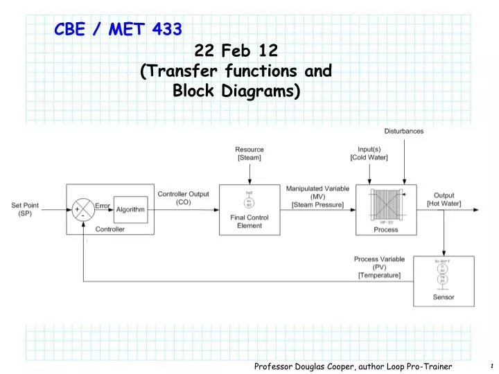
CBE / MET 433 22 Feb 12 (Transfer functions and Block Diagrams) Professor Douglas Cooper, author Loop Pro-Trainer
What are Valve CharacteristicsInherent Characteristics • The three most common valve characterizations are equal percentage, linear, and quick opening Professor Douglas Cooper, author Loop Pro-Trainer
What are Valve CharacteristicsInstalled Characteristics • In many process applications the pressure drop across a valve varies with the flow. In these instances an equal percentage valve will act to linearize the process. Equal percentage valves are the most commonly used control valves. • How do you know what inherent valve characteristic to choose to get a linear installed characteristic? • The correct selection of valve characteristic to linearize the process gain will ease the tuning process and make for a robust system. • Most times this selection is through experience, guesswork or the valve manufacturer’s recommendation. Professor Douglas Cooper, author Loop Pro-Trainer
Feedback Block Diagram Transmitter Transducer Valve Energy Transfer Controller Process
Feedback Block Diagram + + + -
Open Loop vs Closed Loop Transfer Function (R(s)=0) Open Loop: + + + - Closed Loop:
Transfer Functions (Chap 3-5) Define: For heated, stirred tank: + + + + + + - -