Download
1 / 108
1.08k likes | 1.19k Views
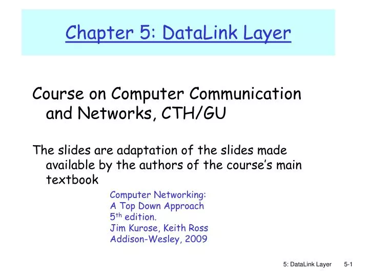
Course on Computer Communication and Networks, CTH/GU The slides are adaptation of the slides made available by the authors of the course’s main textbook. Chapter 5: DataLink Layer. Computer Networking: A Top Down Approach 5 th edition. Jim Kurose, Keith Ross Addison-Wesley, 2009.

E N D
Course on Computer Communication and Networks, CTH/GU The slides are adaptation of the slides made available by the authors of the course’s main textbook Chapter 5: DataLink Layer Computer Networking: A Top Down Approach 5th edition. Jim Kurose, Keith RossAddison-Wesley, 2009 5: DataLink Layer
Our goals: understand principles behind data link layer services: error detection, correction sharing a broadcast channel: multiple access link layer addressing reliable data transfer, flow control: done! instantiation and implementation of various link layer technologies Chapter 5: The Data Link Layer data-link layer has responsibility of transferring frames from one node to adjacent node over a link 5: DataLink Layer
5.1 Introduction and services Framing 5.2 Error detection and correction 5.3Multiple access protocols LAN technology 5.5 Ethernet 5.6 Interconnection 5.4 Link-Layer Addressing 5.7 PPP 5.9 A day in the life of a web request (5.8 Link Virtualization: ATM and MPLS) Link Layer 5: DataLink Layer
Datagram transferred by different link protocols over different links: e.g., Ethernet on first link, frame relay on intermediate links, 802.11 on last link Each link protocol provides different services e.g., may or may not provide rdt over link transportation analogy trip from Princeton to Lausanne limo: Princeton to JFK plane: JFK to Geneva train: Geneva to Lausanne tourist = datagram transport segment = communication link transportation mode = link layer protocol travel agent = routing algorithm Link layer: context 5: DataLink Layer
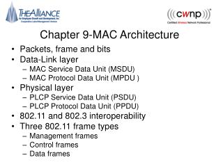
in each and every host link layer implemented in “adaptor” (aka network interface card NIC) E.g. Ethernet card, 802.11 card implements link, physical layer attaches into host’s system buses combination of hardware, software, firmware application transport network link link physical Where is the link layer implemented? host schematic cpu memory host bus (e.g., PCI) controller physical transmission network adapter card 5: DataLink Layer
sending side: encapsulates datagram in frame adds error checking bits, rdt, flow control, etc. receiving side looks for errors, rdt, flow control, etc extracts datagram, passes to upper layer at receiving side Adaptors Communicating datagram datagram controller controller receiving host sending host datagram frame 5: DataLink Layer
Link Layer Services • Framing, link access: • encapsulate datagram into frame, adding header, trailer • channel access if shared medium • “MAC” addresses used in frame headers to identify source, dest • different from IP address! • Reliable delivery between adjacent nodes, flow ctrl • Control when errors + pace between adjacent sending and receiving nodes • we learned how to do this already (chapter 3)! • seldom used on low bit error link (fiber, some twisted pair) • wireless links: high error rates • Q: why both link-level and end-end reliability? 5: DataLink Layer
Link Layer Services (more) • Error Detection: • errors caused by signal attenuation, noise. • receiver detects presence of errors: • signals sender for retransmission or drops frame • Error Correction: • receiver identifies and corrects bit error(s) without resorting to retransmission 5: DataLink Layer
5.1 Introduction and services Framing 5.2 Error detection and correction 5.3Multiple access protocols LAN technology 5.5 Ethernet 5.6 Interconnection 5.4 Link-Layer Addressing 5.7 PPP 5.9 A day in the life of a web request (5.8 Link Virtualization: ATM and MPLS) Link Layer 5: DataLink Layer
Framing • to detect possible bit stream errors in the physical layer, the data link layer groups bits from the network layer into discrete frames • the receiver must be able to detect the beginning and the end of the frame Example methods: • Clock-based + Character count : physical-clock synchronization: much dependent on clock drifts + the counter could be garbled up during transmission 5: DataLink Layer
Byte Stuffing flag byte pattern in data to send • <01111110> delimits beginning, end of frame • “data transparency”: data field must be allowed to include <01111110> • Q: is received <01111110> data or flag? • Sender: adds (“stuffs”) extra <01111110> byte after each <01111110> data byte 01 1 1 1 1 10 flag byte pattern plus stuffed byte in transmitted data • Receiver: • two 01111110 bytes in a row: discard first byte, continue data reception • single 01111110: flag byte 5: DataLink Layer
Framing techniques: examples (cont) ... Physical layer coding violation: exploits special encodings at the physical layer, e.g. Manchester encoding (see next …) 5: DataLink Layer
Encoding Problem:Simple binary encoding (aka Non-Return to Zero, NRZ) introduces problems: • consecutive 0’s or 1’s can lead to a situation called baseline wander (hard to distinguish signal values) • hard to recover the clock More robust encoding: • Manchester: XOR NRZ with clock 5: DataLink Layer
5.1 Introduction and services Framing 5.2 Error detection and correction 5.3Multiple access protocols LAN technology 5.5 Ethernet 5.6 Interconnection 5.4 Link-Layer Addressing 5.7 PPP 5.9 A day in the life of a web request (5.8 Link Virtualization: ATM and MPLS) Link Layer 5: DataLink Layer
Error Detection • EDC= Error Detection and Correction bits (redundancy) • D = Data protected by error checking, may include header fields • Error detection not 100% reliable! • protocol may miss some errors, but this should happen only rarely • larger EDC field yields better detection and correction 5: DataLink Layer
Parity Checking Two Dimensional Bit Parity: Detect and correct single bit errors Single Bit Parity: Detect single bit errors 0 0 5: DataLink Layer
TCP (UDP)’s checksum: segment contents = sequence of 16-bit integers checksum: addition (1’s complement sum) of segment contents sender puts checksum value into UDP (TCP) checksum field Internet checksums • Cyclic redundancy check (CRC) • data bits, D = binary number • consider r+1 bit pattern (generator), G • goal: compute r CRC bits, R, such that • <D,R> exactly divisible by G (modulo 2) • receiver knows G, divides <D,R> by G. If non-zero remainder: error detected! • can detect errors on less than r+1 bits • International standards for G (CRC polynomials) 5: DataLink Layer
CRC Example Recall we want: D.2r XOR R = nG equivalently: if we divide D.2r by G, want remainder R D.2r G R = remainder[ ] 5: DataLink Layer
5.1 Introduction and services Framing 5.2 Error detection and correction 5.3Multiple access protocols LAN technology 5.5 Ethernet 5.6 Interconnection 5.4 Link-Layer Addressing 5.7 PPP 5.9 A day in the life of a web request (5.8 Link Virtualization: ATM and MPLS) Link Layer 5: DataLink Layer
Multiple Access Links and Protocols Two types of “links”: • point-to-point • PPP for dial-up access • point-to-point link between Ethernet switch and host • broadcast (shared wire or medium) • Ethernet • upstream HFC • 802.11 wireless LAN humans at a cocktail party (shared air, acoustical) shared wire (e.g., cabled Ethernet) shared RF (e.g., 802.11 WiFi) shared RF (satellite) 5: DataLink Layer
Multiple Access protocols • single shared broadcast channel • two or more simultaneous transmissions by nodes: interference • collision if node receives two or more signals at the same time multiple access protocol • distributed algorithm that determines how nodes share channel, i.e., determine when node can transmit • communication about channel sharing must use channel itself! • no out-of-band channel for coordination 5: DataLink Layer
Ideal Mulitple Access Protocol Broadcast channel of rate R bps 1. When one node wants to transmit, it can send at rate R. 2. When M nodes want to transmit, each can send at average rate R/M 3. Fully decentralized: • no special node to coordinate transmissions 4. Simple 5: DataLink Layer
MAC Protocols: a taxonomy Three broad classes: • Channel Partitioning • divide channel into smaller “pieces” (time slots, frequency); allocate piece to node for exclusive use • Random Access • allow collisions; “recover” from collisions • “Taking turns” • tightly coordinate shared access to avoid collisions Recall goal: efficient, fair, simple, decentralized 5: DataLink Layer
Channel Partitioning MAC protocols: TDMA, FDMA FDMA: frequency division multiple access • each station assigned fixed frequency band • unused transmission time in frequency bands goes idle • example: 6-station LAN, 1,3,4 have pkt, frequency bands 2,5,6 idle TDMA: time division multiple access • access to channel in "rounds" • each station gets fixed length slot (length = pkt trans time) in each round • unused slots go idle • example: 6-station LAN, 1,3,4 have pkt, slots 2,5,6 idle frequency bands 5: DataLink Layer
Channel Partitioning CDMA CDMA: Code Division Multiple Access • allows each station to transmit over the entire frequency spectrum all the time. • simultaneous transmissions are separated using coding theory. • used mostly in wireless broadcast channels (cellular, satellite, etc) – we will study it in the wireless context • has been ”traditionally” used in the military Observe: MUX= speak person-to-person in designated space CDMA= ”shout” using different languages: the ones who know the language will get what you say 5: DataLink Layer
Random Access Protocols • When node has packet to send • transmit at full channel data rate R. • no a priori coordination among nodes • two or more transmitting nodes ➜ “collision”, • random access MAC protocol specifies: • how to detect collisions • how to recover from collisions (e.g., via delayed retransmissions) • Examples of random access MAC protocols: • slotted ALOHA • ALOHA • CSMA, CSMA/CD, CSMA/CA 5: DataLink Layer
Assumptions: all frames same size time divided into equal size slots (time to transmit 1 frame) nodes start to transmit only at slot beginning nodes are synchronized if 2 or more nodes transmit in slot, all nodes detect collision Operation: when node obtains fresh frame, transmits in next slot if no collision: node can send new frame in next slot if collision: node retransmits frame in each subsequent slot with prob. p until success Slotted ALOHA 5: DataLink Layer
Pros single active node can continuously transmit at full rate of channel highly decentralized: only slots in nodes need to be in sync simple Cons collisions, wasting slots idle slots nodes may be able to detect collision in less than time to transmit packet clock synchronization Slotted ALOHA 5: DataLink Layer
At best: channel use for useful transmissions 37% of time! Slotted Aloha efficiency Efficiency : long-run fraction of successful slots (many nodes, all with many frames to send) Q: max fraction of successful transmissions? A:Suppose N stations, each transmits in slot with probability p • prob. successful transmission is: P[specific node succeeds]=p (1-p)(N-1) P[any of N nodes succeeds] = N p (1-p)(N-1) Efficiency = 1/e = .37 LARGE N 5: DataLink Layer
Pure (unslotted) ALOHA • unslotted Aloha: simpler, no synchronization • pkt needs transmission: • send without awaiting for beginning of slot • collision probability increases: • pkt sent at t0 collide with other pkts sent in [t0-1, t0+1] 5: DataLink Layer
0.4 0.3 Slotted Aloha protocol constrains effective channel throughput! 0.2 0.1 Pure Aloha 1.5 2.0 0.5 1.0 G = offered load = #frames per frame-time Pure Aloha (cont.) P(success by any of N nodes) = N p . (1-p)2N = i.e. N p P(no other node transmits in [p0-1,p0] . P(no other node transmits in [p0,p0+1] =(as n -> infty …) 1/(2e) = .18 S = throughput = “goodput” (success rate) 5: DataLink Layer
CSMA: Carrier Sense Multiple Access CSMA: listen before transmit: • If channel sensed busy, defer transmission • back-off, random interval • If/when channel sensed idle: • p-persistent CSMA: transmit immediately with probability p; with probablility 1-p retry after random interval • non-persistent CSMA: transmit after random interval human analogy: don’t interrupt others! 5: DataLink Layer
CSMA collisions spatial layout of nodes along ethernet collisions can occur: Due to propagation delay, two nodes may not hear each other’s transmission collision: entire packet transmission time wasted note: role of distance and propagation delay (d)in determining collision (collision-detection delay = 2d) 5: DataLink Layer
CSMA/CD (Collision Detection) CSMA/CD: carrier sensing, deferral as in CSMA • colliding transmissions aborted, reducing channel wastage • persistent or non-persistent retransmission collision detection: • easy in wired LANs: measure signal strengths, compare transmitted, received signals • different in wireless LANs: transmitter/receiver not “on” simultaneously; collision at the receiver matters, not the sender human analogy: the polite conversationalist 5: DataLink Layer
“Taking Turns” MAC protocols channel partitioning MAC protocols: • share channel efficiently and fairly at high load • inefficient at low load: delay in channel access, 1/N bandwidth allocated even if only 1 active node! Random access MAC protocols • efficient at low load: single node can fully utilize channel • high load: collision overhead “taking turns” protocols look for best of both worlds! 5: DataLink Layer
“Taking Turns” MAC protocols Token passing: • control token-frame passed from one node to next sequentially. • not pure broadcast • concerns: • token overhead • latency • single point of failure (token) 5: DataLink Layer
IEEE 802.4 Standard (General Motors Token Bus)(not in must-study material) Contention systems limitation: worst-case delay until successful transmission is unlimited => not suitablefor real-time traffic Solution: token-passing, round robin • token = special control frame; only the holding station can transmit; then it passes it to another station, i.e. for token bus, the next in the logical ring • 4 priority classes of traffic, using timers • Logical ring-maintenance: distributed strategy • Robust, somehow complicated though 5: DataLink Layer
IEEE Standard 802.5 (Token Ring)(not in must-study material) Motivation: instead of complicated token-bus, have a physical ring Principle: Each bit arriving at an interface is copied into a 1-bit buffer (inspected and/or modified); then copied out to the ring again. • copying step introduces a 1-bit delay at each interface. 5: DataLink Layer
Token Ring operation • to transmit a frame, a station is required to seize the token and remove it from the ring before transmitting. • bits that have propagated around the ring are removed from the ring by the sender (the receiver in FDDI). • After a station has finished transmitting the last bit of its frame, it must regenerate the token. 5: DataLink Layer
IEEE 802.5 Ring: Maintenance (not in must-study material) Centralised: a “monitor” station oversees the ring: • generates token when lost • cleans the ring when garbled/orphan frames appear If the monitor goes away, a convention protocol ensures that another station is elected as a monitor (e.g. the one with highest identity) If the monitor gets ”mad”, though….. 5: DataLink Layer
IEEE 802.5 Ring: Priority Algorithm (not in must-study material) Station S upon arrival of frame f: set prior(f) := max{prior(f), prior(S)} forward(f) upon arrival of T if prior(T)>prior(S) then forward(T) else send own frame f with prior(f):=0 wait until f comes back prior(T):=prior(f) forward(T) 5: DataLink Layer
Reservation-based protocols Distributed Polling – Bit-map protocol: • time divided into slots • begins with N short reservation slots • station with message to send posts reservation during its slot • reservation seen by all stations • reservation slot time equal to channel end-end propagation delay (why?) • after reservation slots, message transmissions ordered by known priority 5: DataLink Layer
Summary of MAC protocols • What do you do with a shared media? • Channel Partitioning, by time, frequency or code • Time Division, Frequency Division • Random partitioning (dynamic), • ALOHA, S-ALOHA, CSMA, CSMA/CD • carrier sensing: easy in some technologies (wire), hard in others (wireless) • CSMA/CD used in Ethernet • CSMA/CA used in 802.11 • Taking Turns • polling, token passing • Bluetooth, FDDI, IBM Token Ring 5: DataLink Layer
5.1 Introduction and services Framing 5.2 Error detection and correction 5.3Multiple access protocols LAN technology 5.5 Ethernet 5.6 Interconnection 5.4 Link-Layer Addressing 5.7 PPP 5.9 A day in the life of a web request (5.8 Link Virtualization: ATM and MPLS) Link Layer 5: DataLink Layer
Ethernet “dominant” wired LAN technology: • cheap $20 for 100Mbs! • first widely used LAN technology • Simpler, cheaper than token LANs and ATM • Kept up with speed race: 10 Mbps – 10 Gbps Metcalfe’s Ethernet sketch 5: DataLink Layer
Ethernet: uses CSMA/CD A: sense channel, if idle then { transmit and monitor the channel; If detect another transmission then { abort and send jam signal; update # collisions; delay as required by exponential backoff algorithm; goto A } else {done with the frame; set collisions to zero} } else {wait until ongoing transmission is over and goto A} 5: DataLink Layer
Ethernet’s CSMA/CD (more) Jam Signal: make sure all other transmitters are aware of collision; 48 bits; Exponential Backoff: • Goal: adapt retransmission attempts to estimated current load • heavy load: random wait will be longer • first collision: choose K from {0,1} • (delay is K x frame-transmission time) • after m (<10) collisions: choose K from {0,…, 2^m}… • after ten or more collisions, choose K from {0,1,2,3,4,…,1023} 5: DataLink Layer
Ethernet (CSMA/CD) Limitation • Recall: collision detection interval = 2*Propagation delay along the LAN • This implies a minimum frame size and/or a maximum wire length Critical factor: a = 2 * propagation_delay /frame_transmission_delay 5: DataLink Layer
Star topology • bus topology popular through mid 90s • all nodes in same collision domain (can collide with each other) • today: star topology prevails (more bps, shorter distances) • Hub or active switch in center • (more in a while) switch bus: coaxial cable star 5: DataLink Layer
CSMA/CD efficiency • Tprop = max prop between 2 nodes in LAN • ttrans = time to transmit max-size frame • Much better than ALOHA, but still decentralized, simple, and cheap 5: DataLink Layer