Download
1 / 7
70 likes | 263 Views
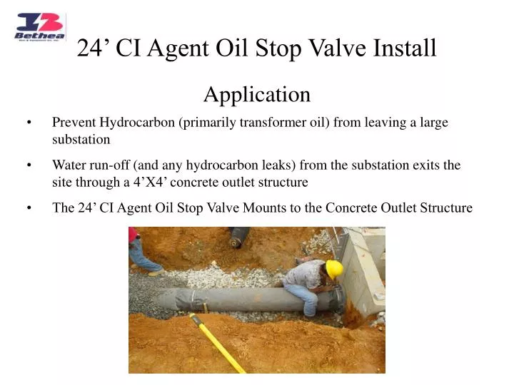
24’ CI Agent Oil Stop Valve Install. Application. Prevent Hydrocarbon (primarily transformer oil) from leaving a large substation Water run-off (and any hydrocarbon leaks) from the substation exits the site through a 4’X4’ concrete outlet structure

E N D
24’ CI Agent Oil Stop Valve Install Application • Prevent Hydrocarbon (primarily transformer oil) from leaving a large substation • Water run-off (and any hydrocarbon leaks) from the substation exits the site through a 4’X4’ concrete outlet structure • The 24’ CI Agent Oil Stop Valve Mounts to the Concrete Outlet Structure
Installation: Step 1 & 2 • Place a gravel bed for the CI Agent Oil Stop Valve to rest on. The gravel is deep enough to allow the flange to center over the inlet holes that lead into the concrete outlet structure. The gravel bed is sloped to allow a ½% grade toward the outlet structure. • Mount the flanged 6’ Section of the CI Agent Oil Stop Valve with gasket (included) to the concrete outlet structure using ½”X 6” Length concrete anchors (included).
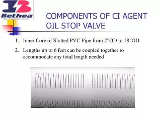
Installation Step: 3 • Connect the 6’ sections of the CI Agent Oil Stop Valve together. • One end of the CI Agent Oil Stop Valve has a belled end which connects to the next non-belled section. The sections are not solvent welded together. • Each 6’ section has a rubber collar that overlaps the previous 6’ section
Installation Step: 4 • Tighten a Stainless Steel Clamp (Included) using a flat head screw driver over each rubber collar.
Installation Step: 5 • Place Gravel over the entire length of the CI Agent Oil Stop Valve
For Additional Information Contact Bethea Tool & Equipment Company Michael Gudger (Regional Sales Manager) Ph# 770-436-6386 Fx# 770-436-9743 E-mail: msgudger@bellsouth.net Web: http://www.betheatool.com