Download
1 / 28
280 likes | 372 Views
Linac to IP Simulations with QMUL High-Throughput Cluster. Philip Burrows, for Glen White Queen Mary, University of London July 2004. Aims Fast Feedback Systems at TESLA Multi-bunch simulations for TESLA Future plans. Aims.

E N D
Linac to IP Simulations with QMUL High-Throughput Cluster Philip Burrows, for Glen White Queen Mary, University of London July 2004 • Aims • Fast Feedback Systems at TESLA • Multi-bunch simulations for TESLA • Future plans
Aims • Study performance of accelerators with multi-bunch tracking Linac-IP. • Integrated test environment- all technologies/ all simulation environments. • Provide database of IP parameters resulting from simulations for Particle/Accelerator Physics community (Lumi,Backgrounds etc).
Performance of TESLA with Position + Angle Intra-train Feedbacks • Examine luminosity performance of TESLA with multi-bunch tracking through Linac and BDS (currently TDR BDS). • Include short+long range wakes in Linac structures, and therefore effects of systematic bunch distortions (bananas) at IP beam-beam interaction. • Study effectiveness of position and angle fast beam-based feedback systems.
Beam-Beam Interaction • Beam-beam EM interactions at IP provide detectable FB signal. • Beam-beam interactions modelled with GUINEA-PIG or CAIN. • Kick angle and percentage luminosity loss for different vertical beam offsets shown.
Detect beam-beam kick with BPM(s) 1 or either side of IP. • Feed signal through digital feedback controller to fast strip-line kickers either side of IP. TESLA Fast Feedback Systems:Position Feedback
FFS TESLA Fast Feedback Systems:Angle Feedback • Normalised RMS vertical orbit in TESLA BDS due to 70nm RMS quadrupole vibrations. • Correct IP angle crossing at IP by kicking beam at entrance of FFS (~1000m). • No significant sources of angle jitter beyond this point as all subsequent quads at same IP phase.
TESLA Fast Feedback Systems:Angle Feedback • Place kicker at point with relatively high b function and at IP phase. • Can correct ~130 mrad at IP (>10sy’) with 3x1m kickers. • BPM at phase 900 downstream from kicker. • To cancel angular offset at IP to 0.1sy’ level: • BPM 1 : required resolution ~ 0.7mm, FB latency ~ 4 bunches. • BPM 2 : required resolution ~ 2mm, FB latency ~ 10 bunches.
Banana Bunches • Short-range wakefields acting back on bunches cause systematic shape distortions: • Z-Y plane of a sample bunch: • Only small increase in vertical emittance, but large loss in luminosity performance with head-on collisions due to strong beam-beam interaction. • Change in beam-beam dynamics from gaussian bunches.
Banana Bunch Dynamics • Luminosity of a sample bunch over range of position and angle offsets. • Wait for IP and ANG FB systems to ‘zero’ – then fine tune by stepping in y then y’ using LUMI monitor to find optimum collision conditions.
Luminosity Feedback TESLA IR Fast Lumi monitor allows bunch-bunch readout of e+e- pair hits which are at Max at Max lumi
Multi-Bunch Simulations at QMUL • Track >500 bunches through Linac, BDS and IP to observe dynamics of fast feedback correction and determine estimate of train luminosity. • Typical simulation times on modern PC 40 hours+ depending on simulation parameters (per seed). • To gauge performance for a variety of parameters/sim environments/machines need many cpu hours. • QMUL high-throughput cluster: GRID cluster development. Currently 32 * Dual Athlon2400+ (64 CPUs). • Currently being upgraded to ~320 CPUs with addition of 2.8 GHz P4 Xeon Processors.
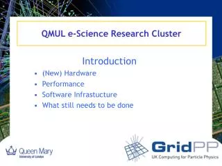
QMUL High-Throughput Cluster • QMUL Test GRID cluster- http://194.36.10.1/cluster • Boxes run Redhat 9 Linux – have 100 Unix Matlab licenses.
Linac Simulation • PLACET: • Structure Misalignment: 0.5mm RMS y, 0.3mrad y’ error. • BPM misalignment: 25mm (y). • Apply 1-1 steering algorithm. • Choose lattice that gives approx. 50% vertical emittance growth. (single bunch tracking). • Injection: 0.2,0.5,1.0s RMS error. • Misalign Quads 100nm RMS in y. • Detune structures. • Generate 500 bunches (multiple random seeds).
PLACET Output • Electron beam at LINAC exit • y (left), emittance (right). • Long-range wakes have strong effect on bunch train. • Need to perform steering on plateux not first bunch- slow.
BDS/IP Simulation • MATMERLIN: • Random jitter on quads = 35nm RMS. • Add 1.4ppm energy jitter on e- bunches (simulates passage of e-’s through undulator). • Track 80,000 macro-particles per bunch. • Feedback (Simulink model in Matlab): • BPM resolution: 2mm (ang FB) 5mm (position FB) • Kicker errors: 0.1% RMS bunch-bunch. • Beam-beam interaction (GUINEAPIG): • Input macro-beam from MatMerlin BDS (non-gaussian). • Calculates Lumi & Beam-Beam kick. • Produces e+e- pairs -> track through solenoid field and count number hitting LCAL first layer for Lumi FB signal.
Position Feedback • Corrects < 10 bunches. • Corrects to finite Dy due to banana bunch effect. • Vertical Beam-Beam scan @ bunch 150.
IP Feedback 5 Bunch e+e- Int. Signal • Corrects < 10 bunches. • Corrects to finite Dy due to banana bunch effect. • Vertical Beam-Beam position scan @ bunch 150: luminosity
Angle Feedback • Angle scan after 250 bunches when position scan complete. • Noisy for first ~100 bunches (HOM’s). • FB corrects to <0.1 sy’
Luminosity • Luminosity through bunch train showing effects of position/angle scans (small). • Total luminosity estimate: L(1-500) + L(450-500)*(2820-500)
Multiple Seed Run (No HOMs) No GM m = 1.0 ± 0.005 GM ( 35nm BDS, 100nm Linac) m = 0.95 ± 0.1 GM + 0.2s Inj. Jit m = 0.92 ± 0.1 • Luminosity fraction compared with mean no-Ground Motion case.
Effect of Lumi-Scan • After position scan • After position and angle scan • Effect of Pos & Ang Lumi scans compared with start of pulse with FB only. • GM + 0.2 s RMS Injection error data.
LC Simulation Web Page • Store all beam data from simulation runs online • http://hepwww.ph.qmul.ac.uk/lcdata
Summary and Future Plans • Facility for multiple processing of accelerator codes set-up. • Used to test TESLA performance with Fast-Feedback. • Need to understand lumi performance & optimise. • Incorporate other feedbacks in linac and BDS. • Crab cavity angle FB. • New BDS lattice(s). • Collimator Wakes. • Similar tests with NLC (&CLIC)… • New people at QMUL to work on simulations: • Tony Hartin (Phys. Programmer). • Shah Hussain (PhD Student).
F.O.N.T. IR Layout With FB System G.R.White: 13/09/2014
F.O.N.T. IR Pair Backgrounds • e+e- Pairs and g’s produced in Beam-Beam field at IP • Interactions with material in the IR produces secondary e+e- ,g, and neutron radiation • Study background encountered in Vertex and tracking detectors with and without FB system and background in FB system itself • Use GEANT3 for EM radiation and Fluka99 for neutrons G.R.White: 13/09/2014
F.O.N.T. EM Backgrounds at BPM • Absorption of secondary emission in BPM striplines source of noise in Feedback system • System sensitive at level of about 3 pm per electron knocked off striplines • Hence, significant noise introduced if imbalanced intercepted spray at the level of 105 particles per bunch exists • GEANT simulations suggest this level of imbalance does not exist at the BPM location z=4.3m for secondary spray originating from pair background G.R.White: 13/09/2014
F.O.N.T. Detector EM Backgrounds • Insertion of feedback system at z=4.3 m has no impact on secondary detector backgrounds arising from pair background • Past studies suggest backgrounds adversely effected only when feedback system installed forward of z=3 m G.R.White: 13/09/2014
F.O.N.T. Detector n Backgrounds Sum Over all Layers: Hits/cm2/1 MeV n equiv./yr Default IR: 5.5 ± 0.8 × 10⁹ IR with FB: 6.6 ± 1.3 × 10⁹ (neutrons/cm2/1 MeV n equiv./yr) VTD Layer • No significant increase in neutron flux in vertex detector area seen arising from pair background • More statistics being generated G.R.White: 13/09/2014