Download
1 / 33
330 likes | 428 Views
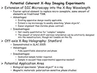
Really Fast X-ray Imaging Instruments. John Oertel Team Leader for Diagnostic Engineering and Operations Presented to LANL Critical Skills program June 26, 2002. Outline. Why do you need a <100 ps x-ray imager? The facilities they operate at Block diagram a gated x-ray imager

E N D
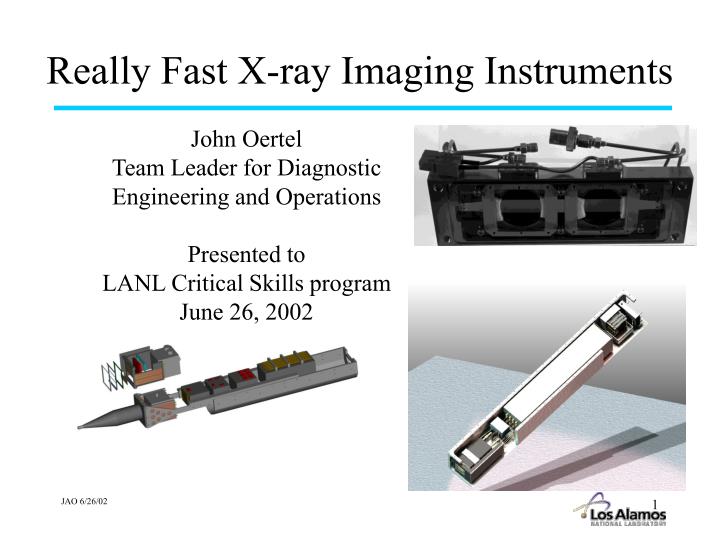
Really Fast X-ray Imaging Instruments John Oertel Team Leader for Diagnostic Engineering and Operations Presented to LANL Critical Skills program June 26, 2002
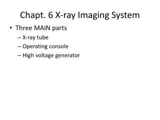
Outline • Why do you need a <100 ps x-ray imager? • The facilities they operate at • Block diagram a gated x-ray imager • Some specifications • X-ray imaging basics • X-ray gating basics • Characteristics • Developments • Applications • The future
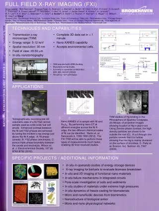
Why? In order to minimize motional blurring and freeze material velocities of > 10 7 cm/s, spatial resolution of 5 mm and gate times of 50 ps are required.One way to gate images from an x-ray pinhole camera is to propagate a high-voltage gate pulse across a microwave transmission deposited on the front surface of a Microchannel Plate.
The Facilities Nova Omega Trident NIF Others…
6 channel Trigger circuit delay circuit Pulsers @ 6 chan. of 4.5 kV, variable pulsewidth, Impedance and 50 ohm matching circuit 50 Ω to 6.25 Ω 4 kV phosphor bias Phosphor Film pac with CCD camera option &fiberoptic MCP module Front-end Filters taper TIM Connector DC bias for MCP +/- 1000 V Impedance matching circuit 6.25Ω to 50 Ω Monitor circuit Block Diagram Connector includes: 1 - 10 volt trigger 3 - 15 volt DC power 3 - fiberoptics 2 - Nitrogen or water cooling lines 1 - High bandwidth monitor 1- Ground line 15 - multi-wire twisted pair
Typical Specifications 40 mm MCP typical 4 Au transmission lines 16 data channels, 4 images/ strip Variable gain Filtering 12x, 8x, 4x and 2x magnifications Insertable or flange mounted Film or CCD image capture 100 eV to 10 keV sensitivity 5 mm spatial resolution 80 ps temporial resolution, some are adjustable a few ns Film or CCD readout
Imaging X-rays with Pinholes has Advantages and Disadvantages • Pros: • Simple • Good signal to noise ratio • Broadband energy transmission • Inexpensive technology for multiple channels • Cons: • Low flux due to small solid angles • Have to get pinhole close to TCC for best resolution
I/I(0) 1.0 R q q L a kasinq 0 3.83 -3.83 Airy pattern consists of a bright central disk surrounded by a system of concentric alternately dark and bright rings. The first zero occurs at kasinq = 3.83 kasinq = 3.83 2p/l asinq = 3.83, sinq = q/R, k = 2p/l, 2a = d q = 1.22 Rl/d
Geometric Optics image plane object plane r q d/2 q L2 L1 tany = q/ L1+L2 = d/2L2 q = d/2(L1 + L2/L2) q y The geometric part d/2 L2 L1 Putting the diffraction and geometric parts together setting S q = 0 and taking derivative with respect to d gives: The optimum pinhole diameter is therefore: 0 = (L1/L2+1)1/2 - 1/d^2(1.22 l L1) d = 2.44 l L1 (M/M+1)
Spatial Resolution Depends Upon Diffraction and Geometric Factors Far field (Fraunhofer) D>>l vs. Near field (Fresnel) D~l l = 1.54 x 10 -10 m, D = 5 x 10⁻⁶ m q1 = 1.22lL1/d, diffraction of circular aperture q2 = d/2(L1/L2+1) geometric optics Minimized source produces a optimum aperture for given E Q(d) = q1 +q2 d = 2.44lL1(M/M+1)
Most x-ray imagers are designed to get the MCP as close as possible to TCC without clipping beams
Micro Channel Plate Module fiberoptic faceplate with P-11 phosphor and vacuum seal or fiberoptic w/ P-20 for CCD All components are off-the-shelf and interchangeable. Be light seal 50Ω to 6.25Ω tapered transmission lines MCPs 3 - 105mmX35mm 6 - strips @ 13 mm wide
c e e = 3.7 Vp = Rout (Vin)^2 E Vout = Rin Gating is provided by launching a short (<200 ps) ~1kV voltage pulse across a microstrip transmission line coated on the MCP. A photoelectron signal produced at the front surface of the MCP is then only amplified during the transit time of the voltage pulse across a given point on the microstrip. Vp =1.5 cm/100 ps 1000 A Gold 5000 A Copper 50 A Chromium 6.6 mm Pin E = Pout 25 W 50 W 25 W With E = 90% V in = 2500 V R in = 50 W Rout = 12.5 W V out = 1185 volts DC Bias 12.5 W 0 to -300 VDC - 2500 Volts, < 200 ps FWHM
Electron Gain in a MCP is very non-linear G ~ Vg g = kn Electron transit time in a MCP channel t tr = m L L D eV t tr ~ 250 ps w/ V = 1 kV and L/D = 40 Temporal Gate Limited by Electron Transit Time Fiberoptic Faceplate with 500 W/cm2 InSnO2 and 0.7 mg/cm2 P-11 phosphor MCP L/D = 40 Kodak 2484 35 mm film n = # of dynodes (26) k = 0.5 g = 13 500 mm e - x-ray e - e - Minimum temporal gate limited by electron transit time. If applied voltage pulse begins to compare in width to t tr it is no longer possible to extract the full gain from a channel. For usable output gains minimum optical gate time tends to be 1/3 t tr. 8o 10 mm 3 kV -300 V
To drive a MCP stripline we use fast high-voltage pulsers 4.04 kV 149.82 ps FWHM tF = 87.75 ps
High Voltage Pulser similar to a Marx bank DC blocking cap • From 2 kV, 200 ps to 4 kV, 150 ps • better differentiation techniques • better interstage capacitors • improved surface conditions • More reliable than previous pulsers • better interstage caps saves transistors • Improved pulse shape consistency • Off-board differentiation simplifies fab • and allows for variable pulse lengths • Reduced pulser drift • 1% zeners 8.2 pF 4 kV, < 200 ps Output shorted stub reverses polarity and reflected signal adds into original resulting in FWHM < 200 ps interstage cap 50 pF other stages and trigger 2.2 kVDC
GXI-3 Resolution Grid ShotTrident Shot T3040704 50 J, 2w, 1 ns square 7 mm wire dia. 25 mm spacing 12x mag. 5 mm pinholes 10 mils Be filtering - 200 VDC bias
Linearity plot Saturation LLNL
2 ns electrical pulse provides a 450 ps FWHM optical gate LLNL
1000Å 1250Å 1500Å 1750Å Detector cathode optimization requires further study What is the optimum cathode coating for a MCP? 3 MCP’s all from same boule All coating were Au 250Å to 2500Å Aluminum - DC source @ 1.6 keV Preliminary results suggest we have not peaked! Does it act the same for a different wavelength?
P-11 Phosphor optimization What phosphor coating density yields the greatest flux? 0.6 mg/cm2 What phosphor coating density yields the best spatial resolution?
25563 Applications
Rayleigh-Taylor instability growth studied in cylindrical convergent geometry using “indirect-drive” on the NOVA laser
GXD Electronic Block Diagram 28VDC Trigger in Imp. Mis-match Ethernet MCP Module pfn Pulser Cards & Power supplies Delay Circuits Trig Circuits PC104 computer CCD P.S. Housekeeping sensors CCD phos DC bias Cooling Monitor Imp. matching Adder circuit pcd
Gated X-ray Imager for the NIF Ethernet unit 4” Embedded Computer 30” - 36” 52” - 58” • Kentech Electronics • HV pulser units (3.5 kV - 4 kV) • Power supplies • Delay generators (50 nsmax.) • Triggering • Monitor • Command/Control 10-12” CCD power supply 2x2x3”, 2 ea. CCD Cooling in external base of airbox MCP Module
MCP Module CCD Cooling lines Phosphor HV SMA Connectors MCP Striplines Terminator Circuit Wing Intensifier Block
Spectral Instruments CCD Camera Power Readout TE Cooling Lines Cooling Block Fiber Optically coupled Pump Out Vacuum Enclosure
Kentech Electronics Pulse Out Dimension based on performance requirements Pulse In MCP Bias +1kV/ -500V 30” - 36” PCD +400V Phosphor Bias +4kV Trigger In Monitor Out +28VDC Computer Interface Pulser Units 4 each 1 1/8” W x 4.92” H
PC 104+ Embedded Computer Embedded Computer PC104/PC104+ Support Cards: Frame Grabber Kentech Interface Housekeeping Ethernet: Electrical/Fiber optic Fiber/Fiber CCD Power Supply 2x2x3”, 2 each