Download
1 / 22
400 likes | 912 Views
Sandipan Ray Suruchi Rao Harini Chandra. Matrix-Assisted Laser Desorption Ionization Time of Flight (MALDI TOF).

E N D
Sandipan Ray Suruchi Rao Harini Chandra Matrix-Assisted Laser Desorption Ionization Time of Flight (MALDI TOF) MALDI is an efficient process for generating gas-phase ions of peptides and proteins for mass spectrometric detection. It is widely used in proteomics research as a high-throughput technique to identify proteins and their post translational modifications.
Master Layout (Part 1) 1 Part 1: Fundamentals of MALDI-TOF MSPart 2: Sample preparation and spotting Part 3: Ionization and detection 2 Matrix-Assisted Laser Desorption Ionization Time-of-flight (MALDI TOF) 1 2 4 3 3 Flight tube 4 Ion source Detector 1.Sample preparation and spotting; 2. Ionization; 3. Separation on the basis of time of flight; 4. Detection 5
Definitions of the components:Part 1 – Fundamentals of MALDI-TOF MS 1 1. Ion source: One of the major components of any MS instrumentation which fragments the sample into an ionic form for further detection. MALDI and ESI are most commonly used for proteins samples 2. Matrix Assisted Laser Desorption Ionization (MALDI): MALDI is an efficient ionization source for generating gas-phase ions of peptides and proteins for mass spectrometric detection.Target analyte embedded in dried matrix-sample is exposed to short, intense pulses from a UV laser. 3. Mass analyzer: The mass analyzer resolves the ions produced by the ionization source on the basis of their mass-to-charge ratios. Various characteristics such as resolving power, accuracy, mass range and speed determine the efficiency of these analyzers. Commonly used mass analyzers include Time of Flight (TOF), Quadrupole (Q) and ion trap. 4. Time-of-Flight (TOF): This is a mass analyzer in which the flight time of the ion from the source to the detector is correlated to the m/z of the ion. 5. Flight tube: Connecting tube between the ion source and detector within which the ions of different size and charge migrate to reach the detector. 2 3 4 5
Definitions of the components:Part 1 – Fundamentals of MALDI-TOF MS 1 6. Reflectron: The reflectron acts as an ion mirror, and extends the flight length without increasing the instrument size. The reflectron compensates for the initial energy spread of ions having the same mass. 7. Reflectron detector: Detects the ions reflected by ion mirror. This over all setup improves the resolution. 8. Detector: The ion detector determines the mass of ions that are resolved by the mass analyzer and generates data which is then analyzed. The electron multiplier is the most commonly used detection technique. 2 3 4 5
Part 1, Step 1: Time-of-Flight Mass Analyzer 1 Linear Mode Flight Tube 2 Detector Ion Source 3 The lighter ions travel faster and strike the detector before the heavier ions. This “time of flight” (TOF) can be correlated with mass of the ion 4 Action Description of the action Audio Narration First show the rectangular tube with the ‘detector’ on the right end & the ‘ion source’ on the left end. Next, show the appearance of the colored circles which must then move towards the ‘detector’ such that the smallest circle moves the fastest & the largest one moves slowly. Once they reach the detector, the text below must be shown. As shown in animation. The time-of-flight analyzer resolves ions produced by the ionization source on the basis of their mass-to-charge ratio. The TOF tube can be operated in the linear mode or the reflectron mode depending on the sample to be detected. In case of small molecules, this mode usually provides sufficient resolution. The generated ions are accelerated towards the detector with the lighter ions travelling through the TOF tube faster than the heavier ions. The flight time of the ions is correlated with the m/z ratio. 5
Part 1, Step 2: 1 Reflectron mode Reflectron detector Flight Tube Reflectron (Ion Mirror) Sample target 2 3 Ion Source 4 Action Description of the action Audio Narration As shown in animation. The TOF analyzer can also be operated in the reflectron mode, which is more commonly used for proteomics studies. A reflectron, which acts as an ion mirror, is incorporated at one end of the TOF tube. This helps in extending the path length and in turn the flight time of the ion without having to increase the actual size of the instrument. This helps to even out any kinetic energy differences between ions having the same mass and thereby improves the resolution. First show the rectangular tube with the ‘reflectron’, ‘detector’ & the ‘ion source’ on the left end. Next, show the appearance of the colored circles which must then move towards the ‘reflectron’ where they get deflected and ultimately reach the ‘reflectron detector’. The smallest circle must move fastest while the largest must move slowly as shown in the animation. 5
1/2 m t = L 2qV0 Part 1, Step 3: 1 Time-of-Flight Equation 2 Where t = time-of-flight (s) m = mass of the ion (kg) q = charge on ion (C) V0 = accelerating potential (V) L = length of flight tube (m) 3 4 Action Description of the action Audio Narration As shown in animation. The time of flight of a charged ion can be calculated by means of the equation shown. The flight time is directly proportional to the square root of mass of the ion. Show appearance of the equation and meaning of each of its terms. 5
Master Layout (Part 2) 1 Part 1: Fundamentals of MALDI-TOF MSPart 2: Sample preparation and spotting Part 3: Ionization and detection 2 Sample Preparation Matrix selection 3 Matrix preparation Sample purification Sample deposition 4 Matrix deposition Drying target Analysis 5
Definitions of the components:Part 2 – Sample preparation and spotting 1 1. In-gel digestion: The in-gel digestion is part of the sample preparation process for the mass spectrometric identification of proteins during the course of proteomic analysis. Protein spots or bands excised from the gels are digested using trypsin. 2. Trypsin:Trypsin is a serine protease found in the digestive system of many vertebrates, where it hydrolyses proteins. It cleaves at the C-terminal of lysine (K) and Arginine (R) residues with the exception of K-proline and R-proline sites. 3. ZipTip: Very small tip like device for removal of salts and other interfering agents from the protein samples before analysis. ZipTips can be incorporated into high throughput robotic devices for automated sample clean up. 4. Sample/Target plate: Multiple well plates on which the samples are spotted. 5. Analytes: The samples that are under study. Analytes may be proteins, peptides or carbohydrates and are ionized prior to mass spectrometric detection. 6. Matrix: Solution containing high concentration of a UV absorbing molecule deposited on sample plate along with samples. It is essential to select a matrix appropriate for the type of sample to be analysed. 7. Ion desorption: A process in which atomic and molecular species residing on the surface of a solid leave the surface and enter the surrounding gas or vacuum. 2 3 4 5
Part 2, Step 1: 1 Trypsin digestion In-gel digestion: Cut out spot 2 Arginine or Lysine Completed gel 3 C-terminal N-terminal Trypsin Digested fragments 4 Action Description of the action Audio Narration The protein sample must be prepared suitably before it can be analyzed by MS. The purified protein of interest is excised from the gel on which it has been electrophoresed and dissolved in a suitable buffer. Trypsin is then added to this in order to carry out digestion of the protein. This enzyme cleaves the protein at the C-terminal of the its arginine & lysine residues unless there is a proline present immediately after. The protein is thus digested into smaller fragments of manageable size. As shown in animation. First show appearance of the grey image on top left with all the spots. Next show the red circle. That black spot must be excised from there and must enter the tube as depicted. Next show a hand adding a solution into the tube with the micropipette which must turn green in color. The tube must then be zoomed into and the brown rectangle interspersed with green region must be shown. The orange object must then be shown which must cleave the rectangle exactly at the green regions. Once it is cleaved, the fragments must separate out as shown below the arrow mark. 5
Part 2, Step 2: 1 Removal of salt, buffers and detergents from the sample 2 3 Filter Digested protein sample 4 Action Description of the action Audio Narration Once the protein sample has been digested, all the salt, buffers and any detergents must be removed from this sample. This can be efficiently done with the help of filters (e.g. ZipTip). It offers several advantages such as quick purification, sample enrichment and ensuring there is no contamination. However, it can purify only limited volume of the sample and also adsorbs some amount of the protein sample thereby leading to losses. As shown in animation. First show the tube with the grey solution in it. Next show the hand with the micropipette in it. This must move into the tube, be held there very briefly and then be removed out again. This must be repeated at least 5 times. Once the hand is outside again, the tip of the micropipette must be zoomed in and the figure in the circle must be shown. Again the white region must be zoomed into and the figure on the right must be shown. 5
Part 2, Step 3: 1 Addition of matrix 2 3 Mixing Sample 4 Action Description of the action Audio Narration The purified protein sample is then mixed with an aromatic matrix compound like a-cyano-4-hydroxycinnamic acid, sinapinic acid etc. in the presence of an organic solvent. The components are then mixed thoroughly. As shown in animation. First show the tube with a grey solution in it. Next show the hand with the micropipette entering the tube. Once it enters, the grey solution must turn blue and the hand must then be removed. Then show this tube being placed in one of the holes in the instrument on the right. 5
Part 2, Step 4: 1 Sample spotting Protein 2 Matrix 3 196 –well MALDI Plate 4 Action Description of the action Audio Narration The solution containing the organic matrix with the embedded analyte is then spotted on to a metallic MALDI sample plate. As shown in animation. First show the grey surface with white spots. Next show the hand with pipette moving down and a liquid being dispensed into one of the spots. This spot must then be zoomed into and the figure on top left must be shown. 5
Master Layout (Part 3) 1 Part 1: Fundamentals of MALDI-TOF MSPart 2: Sample preparation and spotting Part 3: Ionization and detection Laser Matrix & analyte 2 Detector Flight tube 3 MALDI Target plate 4 Peptide spectrum 5
1 Definitions of the components:Part 3 – Ionization and detection • 1. Laser: Light amplification by stimulated emission of radiation (LASER or laser) is a mechanism for emitting electromagnetic radiation. • 2. Matrix & analyte: Solution containing high concentration of UV absorbing molecules embedded with the analyte of interest, deposited on the sample plate. It is essential to select a matrix that is appropriate for the type of sample being analysed. Commonly used matrices are sinapinic acid and a-cyano-4-hydroxycinnamic acid • 3. Sample plate: Plate onto which the matrix-analyte solution is spotted. • 4. Matrix Assisted Laser Desorption Ionization (MALDI): MALDI is an efficient ionization source for generating gas-phase ion of peptides and proteins for mass spectrometric detection.Target analyte embedded in dried matrix-sample is exposed to short, intense pulses from a UV laser. 5. Time-of-Flight (TOF):- This is a mass analyzer in which the flight time of the ion from the source to the detector is correlated to the m/z of the ion. 2 3 4 5
1 Definitions of the components:Part 3 – Ionization and detection 6. Flight tube:- Connecter between the ion source and detector within which the ions of different size and charge fly to reach the detector 7. Detector:- The ion detector determines the mass of ions that are resolved by the mass analyzer and generates data which is then analyzed. The electron multiplier is the most commonly used detection technique. 8. Peptide spectrum: The picks corresponding to individual peptides which are separated on the basis of their m/z ratio. 2 3 4 5
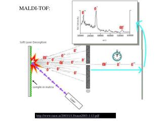
Part 3, Step 1: 1 Ionization Laser Matrix & analyte 2 Detector Flight tube 3 MALDI Target plate 4 Action Description of the action Audio Narration The target plate containing the spotted matrix and analyte is placed in a vacuum chamber with high voltage and short laser pulses are applied. The laser energy gets absorbed by the matrix and is transferred to the analyte molecules which undergo rapid sublimation resulting in gas phase ions. As shown in animation. First show the entire grey apparatus with all the labels and the violet rectangle laser source. Next show a beam emerging from the rectangular box and falling on the white semicircular region. Once this happens, the colored ions must emerge from the white surface as shown in animation. 5
Part 3, Step 2: 1 Resolution & detection Detector Flight tube 2 3 Peptide spectrum 4 Action Description of the action Audio Narration The gas phase ions generated are accelerated and travel through the flight tube at different rates. The lighter ions move rapidly and reach the detector first while the heavier ions migrate slowly. The ions are resolved and detected on the basis of their m/z ratios and a mass spectrum is generated. Parameters such as geometric design, power supply quality, calibration method, sample morphology, ion beam velocity etc. all affect the accuracy of mass detection. As shown in animation. Once the colored circles have appeared, they must move towards the ‘detector’. The smallest blue circles must move the fastest followed by the orange circles and then the green circles. Once all the circles reach the detector, the computer with the spectrum in it must be shown. 5
Interactivity option 1:Step No: 1 1 MALDI can also be used for tandem mass spectrometry studies in combination with two consecutive TOF tubes that are separated by a collision cell. The ion fragment selected from the first TOF tube is further fragmented in the collision cell by bombarding against an inert gas like argon. This technique can be used for protein sequencing studies. Click on the laser to view the working of MALDI-TOF-TOF-MS. 2 Laser Detector 3 TOF 1 TOF 2 4 Reflector Collision cell Results Interacativity Type Options Boundary/limits When the user clicks on the red box marked as ‘laser’ the animation shown must take place. The three circles (blue, red & yellow) must appear which must move towards the violet box. In this only the yellow circle must be selected & move ahead. It must then get fragmented & three smaller circles (green, pink & yellow) must appear which must then travel towards the ‘detector’, with the smallest circle moving fastest. User must click on the red box marked as laser’ after which the animation shown above must appear. 5 Click on the red box marked ‘laser’.
Questionnaire 1 1. Which are the two types of ionization sources used for the Mass Spectrometric analysis of biological samples? a) Fast Atom Bombardment and Chemical Ionization b) Electron Transfer Dissociation and Collision Induced Dissociation c) Matrix Associated Laser Desorption Ionization and Electrospray Ionization d) Electron Transfer Dissociation and Matrix Associated Laser Desorption Ionization 2. Which of the following is not a mass analyzer? a) Time-of-Flight (TOF) b) Quadrupole (Q) c) Ion traps d) MALDI • MALDI is a a) Soft ionization technique b) Hard ionization technique c) Both of them d) None of them 2 3 4 5
Questionnaire 1 4. Which of the following matrix is most suitable of carbohydrate samples? a) CHCA b) Sinapinic acid c) Dithranol d) DHB 5. Which of the following statement is right a) MALDI is more tolerant to salts than ESI b) MALDI is less tolerant to salts than ESI c) Both of them are equally more tolerant to salts d) There is no effect of salts on MALDI and ESI 2 3 4 5
Links for further reading Books: Link, A. J., LaBaer J., Proteomics; A cold spring harbour laboratory manual; cold spring harbour laboratory press. Research papers: 1. Karas, M., Hillenkamp, F. "Laser desorption ionization of proteins with molecular masses exceeding 10,000 daltons". Anal. Chem. 1988, 60, 2299–2301. 2. Karas, M., Glückmann, M., Schäfer, J. Ionization in matrix-assisted laser desorption/ionization: singly charged molecular ions are the lucky survivors. J Mass Spectrom. 2000 ,35,1-12.