Download
1 / 21
250 likes | 575 Views
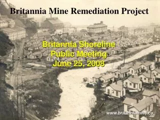
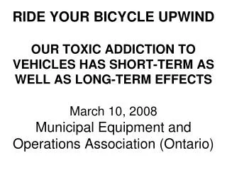
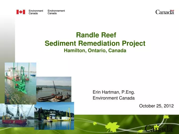
Randle Reef Sediment Remediation Project Hamilton, Ontario, Canada. Erin Hartman , P.Eng . Environment Canada. October 25, 2012. Hamilton Harbour. Randle Reef Sediment Remediation Project Hamilton Harbour , Lake Ontario, Canada. USS. Randle Reef Project Site.

E N D
RandleReefSedimentRemediation ProjectHamilton, Ontario, Canada Erin Hartman, P.Eng. Environment Canada October 25, 2012
Randle Reef Sediment Remediation Project Hamilton Harbour, Lake Ontario, Canada USS Randle Reef Project Site
Randle Reef Site Specifics • Impacted by historic operation of coal gasification plant and steel operations; • Approximately 675,000 m3 of contaminated sediment (PAHs & metals); and • Average total PAH concentration near 5,000 ppm with peaks over 73,000 ppm. • Site Area: ~60 ha (148 acres) • Depth of Water: Ranges from ~4 m to 12 m • Sediment Depth: Ranges from ~0.1 m to >3 m
Basic Project Design • Construct a 7.5 hectare (18.5 acres) Engineered Containment Facility (ECF) over the most highly contaminated sediment (130,000 m3in-situ); • Using primarily hydraulic dredging (minor mechanical dredging component), remove 500,000 m3 and place within ECF;
Isolation Structure • A double steel sheetpile wall with sealed interlocks Sealed interior wall Outer structural wall
Dredging Design • Dredging Challenges: • Dredging of firm clay and volatile management; • Finite capacity of the ECF; • Dredging offsets from existing dock walls; • Residuals management; • Dredging prohibitive in one section due to existing structure stability. U.S. Steel Channel
Site Specific Clean-Up Criteria 100 mg/kg (ppm) Total PAHs based on the consideration of: Background levels of PAHs in the Harbour (30 - 45 mg/kg); Average concentrations of PAHs in the Harbour (~68 mg/kg); Uncontrollable indirect inputs of PAHs to the Harbour (i.e. vehicular emissions); Toxicity data from another similar contaminated sediment site located in Hamilton Harbour as well as Randle Reef itself; Other clean-up criteria for PAH-contaminated sediment sites (NOWPARC -Thunder Bay Canada (150 mg/kg), St. MarysRiver – Sault Ste. Marie (USA) (115 mg/kg)).
Avg [PAHs]=2,000 ppm and toxic Approach to Remediate Sediment Metals exceed SELs Priority 1 Most P1 sediment is contained within ECF footprint. If not, it is dredged and placed within ECF [PAHs]>100 ppm and toxic Priority 2 P2 sediment is dredged and placed within ECF. [PAHs]>100 ppm and nottoxic Priority 3 P3 sediment will be placed in the ECF or capped with a thin-layer of clean sediment [PAHs]<100 ppm andtoxic Metals below SELs Priority 4 P4 sediment left for natural attenuation
PAH Mass Distribution ECF Full
1. Gravity settling of decant water within the ECF2. Polymer-assisted settling in a final settling cell (area between the walls)3. Additional treatment using sand filtration and (GAC) adsorption4. Discharge to Hamilton Harbour Production Dredging – Dredgeate Management
Dredgeate Management Final Settling Cell (tmin = 8.5hrs) Dredge - 1,250 m3/hr Cell 2 Polymer Addition Cell 1 To water treatment plant From polymer tank
Isolation Cap Design US Steel Channel Accommodates intakes and dock wall stability concerns. (with silt & enriched TOC)
ECF Multi-layer Cap: • Foundation Layer - provides a stable surface on which to construct the overlying layers; • Underliner Drainage System - critical for the removal of pore water during consolidation and for the control of groundwater upwelling after consolidation;
ECF Multi-layer Cap: Hydraulic Barrier • Prevents infiltration into the underlying sediments and upwelling of pore water/groundwater into the cap materials.
ECF Multi-layer Cap: Preload • Total anticipated settlement = 85 - 110 mm • 30 – 50 KPa crushed rock • 1 to 1.5 year duration • Porewater channeled to perimeter collection trenches • Pumped & treated
ECF Multi-layer Cap: Drainage Systems Overliner Drainage Underliner Drainage Stormwater Drainage Geomembrane Wick Drains
Draft Construction and Cost Schedule $138.9M ECF Construction Dredging/ Management ECF Capping +Long Term Monitoring $53.5 M $36.4 M $49 M
Thank-you Erin Hartman, P.Eng. Sediment Remediation Unit Environment Canada Tel: 905-336-6009 E-mail: Erin.Hartman@ec.gc.ca