Download
1 / 43
430 likes | 491 Views
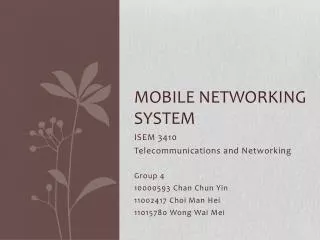
MOBILE SYSTEM AND STANDARD . Radio Technology. Technological drivers of radio technology Hardware: Better batteries,less power consumption, processors with higher performance Link: Better /more sophiscated antennas, modulation and coding, DSPs with higher performance

E N D
Radio Technology • Technological drivers of radio technology • Hardware: Better batteries,less power consumption, processors with higher performance • Link: Better /more sophiscated antennas, modulation and coding, DSPs with higher performance • Network: Mobility support, dynamic resource allocation • Application: Adaptive QoS • Reuse of spectrum through spread spectrum • Despite the trend that newer technologies use higher frequencies, radio BW remains limited • Spread spectrum – distribute the signal over wide frequency range, less susceptive to interference and noise
Radio Technology Problem • Hidden station • A wireless station STA3 does not hear STA1(hidden). Both STA1 & STA3 may start sending at the same time, thus causing contention at STA2 • Eavesdropping • W/less networks are inherently open to eavesdropping. This means that w/less network need protection(strong encryption) • Realibility of wireless connections • w/less network less reliable since its suffer from interference, reflections, dropouts etc.
Radio Technology Problem • Power consumption of wireless devices • Inherently suffer from a power problem, often targeted at low power applications. • Usually a greater distance between the antennas requires more transmission power, thus increases the power consumption • Limited bandwidth, need for frequency licensing • Obtaining a license is costly • Many technologies (WLAN,Bluetooth,Zigbee) use the unlicensed ISM band. This in turn means that interferences between different senders become problem
GSM • Abbreviation for Global System for Mobile Communications • Concurrent development in USA and Europe in the 1980’s • The European system was called GSM and deployed in the early 1990’s
Multiple Access • Each GSM channel uses a TDMA method to support simultaneous calls from multiple subscribers • Mobile terminals transmit in bursts of 576.92 µs • One burst fits into one timeslot • Through feedback signals, the system can ensure that the signals from all users arrive exactly in their assigned time slot, even if propagation distances to and from different users vary over time. • A set of 8 TDMA slots is called a frame. • In GSM, the terminal transmits and receives during different time slots.
GSM Frequencies • Originally designed on 900MHz range, now also available on 800MHz, 1800MHz and 1900 MHz ranges. • Separate Uplink and Downlink frequencies • One example channel on the 1800 MHz frequency band, where RF carriers are space every 200 MHz UPLINK FREQUENCIES DOWNLINK FREQUENCIES 1710 MHz 1785 MHz 1805 MHz 1880 MHz UPLINK AND DOWNLINK FREQUENCY SEPARATED BY 95MHZ
GSM Frequencies • GSM900 • Uplink 890 – 915 MHz • Downlink 935 – 960 MHz. • duplex spacing is 45 MHz • divided into 125 bands with 200 kHz spacing • Carrier frequencies 890.0 MHz + n(0.2) MHz • GSM-1800 • Channel numbers n : 512 – 885 • Carrier frequencies 1710 MHz + (n-511)0.2 MHz • Uplink 1710 – 1785 MHz • Downlink 1805 – 1880 MHz • Duplex spacing of 95 MHz • Better suited to serve densely populated areas • 1800 MHz : smaller range, smaller cells
GSM radio interface – Main characteristics • Carrier bandwidth: 200 kHz • Channels / carrier: 8 • Multiple access: TDMA / FDMA • Duplex: FDD • Gross bit rate pr carrier: 270,833 kbit/s • Modulation: GMSK • Spectrum efficiency: 1.35 bps/Hz • MS: • Sensitivity: -104 (-102) dBm • Typical – 106 dBm • Max. output power: 33 (30) dBm • BTS: • Sensitivity: -104 (-104) dBm • Typical: – 107 dBm • Max. output power: 43 dBm
GSM Channels Downlink • Physical Channel: Each timeslot on a carrier is referred to as a physical channel • Logical Channel: Variety of information is transmitted between the MS and BTS. Different types of logical channels: • Traffic channel • Control Channel Channels Uplink
GSM Architecture Home Location Register Network MgmentCenter BTS = Base Transceiver Station AuC = Authentication Center OMC = Operation and Maintenance Center PSTN = Public Switched Telephone Network ME = Mobile Equipment AuC Equipment ID Visitor Location Register OMC Subscriber Identity Module BTS Mobile switching center ME Data communication network Subscriber Identity Module Base station controller BTS ME Subscriber Identity Module BTS ME PSTN Source: Stallings, 313 Source: Mehrotra, 27
Mobile Station (MS) • MS is the user’s handset and has two parts • Mobile Equipment • Radio equipment • User interface • Processing capability and memory required for various tasks • Call signalling • Encryption • SMS • Equipment IMEI number • Subscriber Identity Module
Subscriber Identity Module • A small smart card • Encryption codes needed to identify the subscriber • Subscriber IMSI number • Subscriber’s own information (telephone directory) • Third party applications (banking etc.) • Can also be used in other systems besides GSM, e.g., some WLAN access points accept SIM based user authentication
Base Station Subsystem • Transcoding Rate and Adaptation Unit (TRAU) • Performs coding between the 64kbps PCM coding used in the backbone network and the 13 kbps coding used for the Mobile Station (MS) • Base Station Controller (BSC) • Controls the channel (time slot) allocation implemented by the BTSes • Manages the handovers within BSS area • Knows which mobile stations are within the cell and informs the MSC/VLR about this • Base Transceiver System (BTS) • Controls several transmitters • Each transmitter has 8 time slots, some used for signaling, on a specific frequency
Network and Switching Subsystem • The backbone of a GSM network is a telephone network with additional cellular network capabilities • Mobile Switching Center (MSC) • An typical telephony exchange (ISDN exchange) which supports mobile communications • Visitor Location Register (VLR) • A database, part of the MSC • Contains the location of the active Mobile Stations • Gateway Mobile Switching Center (GMSC) • Links the system to PSTN and other operators • Home Location Register (HLR) • Contain subscriber information, including authentication information in Authentication Center (AuC) • Equipment Identity Register (EIR) • International Mobile Station Equipment Identity (IMEI) codes for e.g., blacklisting stolen phones
Mobile Switching Centre • MSC: Digital switch for the mobile network • Takes care of the resource management on the A interface towards the BSC and is responsible for call processing • Process a handover decision between two and even three MSCs • A special function is given to the Gateway MSC (G-MSC) which is a MSC that provides access to external networks. • In a PLMN, not every MSC needs to be a GMSC
Visitor Location Register • Initially the VLR was designed as a separate network element to the MSC, today the VLR is integral part of what is called MSC/VLR. • VLR is basically a huge database that administrates the mobility of thousands of subscribers • VLR dynamically administrates the subscribers that are currently present in the very area that the VLR covers • The VLR is the peer to the mobile station during authentication, “Location Updating” • VLR knows a subscriber’s precise location (location area)
Home Location Register • an intelligent database and service control function responsible for management of each subscriber’s records and control of certain services • Responsibilities of the HLR include: • management of service profiles • mapping of subscriber identities (MISDN, IMSI) • supplementary service control and profile updates • execution of supplementary service logic e.g. incoming calls barred. • passing subscription records to VLR • Also the subscriber’s present Location Area Code, which refers to the MSC, which can connect to the MS.
Authentication Centre (more details) • (AuC) is an intelligent database concerned with the regulation of access to the network ensuring that services can be used only by those who are entitled to do so and that the access is achieved in a secure way. • The principle is that the AuC and the SIM have a unique key for every subscriber (Ki) which is used as the basis for generating a response (SRES) to a random number (RAND) generated by the AuC. Only the true SIM will be able to generate the correct response and thus gain access to the network. • The AuC is generally integrated with the HLR. • [Also EIR the Equipment Identity Register - another database that holds a list of ‘allowed’ equipment identities, i.e. ME numbers: white / grey / black lists]
Other Systems • Operations Support System • The management network for the whole GSM network • Usually vendor dependent • Very loosely specified in the GSM standards • Value added services • Voice mail • Call forwarding • Group calls • Short Message Service Center • Stores and forwards the SMS messages • Like an E-mail server • Required to operate the SMS services
Mobile Originating Call (MOC) • If a mobile subscriber initiates a call then the mobile originating call setup procedure applies • This call maybe for • Mobile – mobile in the same PLMN • Mobile – mobile in different PLMN • Mobile – PSTN • The main call setup is done in the MSC • MSC will evaluate if and how a call setup attempt can be served • MSC will route the call according to the type of call and the called directory number.
Mobile Terminating Call (MTC) • If someone intends to call a mobile subscriber he will dial the number of that subscriber • According to the country code and prefix area code, this call request will be routed to a G-MSC of the respective PLMN • This G-MSC will retrieve routing information from the HLR of the called subscriber and direct the call to the currently serving MSC/VLR.
Location Area • Each location area consists of one or more BTS • A mobile station in motion keeps the network informed about changes in the location area • Location area is used in GSM -> to reduce the signalling traffic for paging and registrations (Location Updates) towards the network • In case of a mobile receiving call, the network will page a mobile station not in all cells that belong to a PLMN but only in those cells that belong to the current location area. • When a GSM mobile station is switched on it needs to make itself known towards the network. • If the mobile station has changed its location since it was last switched off, it need to perform a location update
Location update • A location update is performed when: • The mobile is connecting to a cell and discovers that the LAI read is different than the one stored in the mobile • The mobile has been turned on, but not used, for a pre-defined period of time since the last location update (periodic location update) • IMSI detach/attach: • An additional function where the mobile informs that it is turned on or off (in the same LA), saves resources on the radio interface and leads to faster response on incoming calls • Periodic detach • A network functionality where the network assumes that the mobile has been turned off if periodic location update has not been performed and no other activity has been observed for a pre-defined amount of time
LA Update Message Sequence • MS to NEW MSC (via BSS) – location updating request • New MSC to NEW VLR – update location area • New VLR to HLR – update location • HLR to OLD VLR – cancel location • OLD VLR to HLR – cancel location ACK • HLR to NEW VLR – insert subscriber data • NEW VLR to HLR – insert subscriber data ACK • HLR to NEW VLR – update location ACK • NEW VLR to NEW MSC – update location area ACK • NEW VLR to MS – location updating accept
Location Updates • The cells overlap and usually a mobile station can ‘see’ several transceivers (BTSes) • The MS monitors the identifier for the BSC controlling the cells • When the mobile station reaches a new BSC’s area, it requests an location update • The update is forwarded to the MSC, entered into the VLR, the old BSC is notified and an acknowledgement is passed back
Roaming • This allows subscribers to operate in service areas other than the one from which service is subscribed. • When a mobile enters a city or geographic area that is different from its home service area, it is registered as a roamer in the new service area. • Periodically, the MSC issues a global command over each FCC in the system, asking for all mobiles which are previously unregistered to report their MIN and ESN over the RCC for billing purposes • If a particular mobile user has roaming authorization for billing purposes, MSC registers the subscriber as a valid roamer.
How roaming works • The home operator has a 'roaming agreement' with an operator in the visited country that enables the user to use its network. • When phone is switch on your in the foreign country, the mobile phone picks up the radio signals of one of the operators in that country. • This local operator will then 'authenticate' the mobile phone with your home operator (e.g. check if you are a valid customer, whether you are allowed to roam, etc.). • If the home operator responds with a positive authentication, the mobile phone is ready for use. • Note that when roaming, the users have to pay both for calls that you make and receive.
When abroad and “Calling Home” • When abroad and “Calling Home” to a friend, your call is managed by the host operator. • The host operator passes the call via 'international transit' to your home operator. • Your home operator connects you to your friend’s operator and establishes your call. • Who pays for what? • Steps 1 and 2 The host operator charges your home operator a wholesale rate which includes the interconnection costs (“International Transit” and costs for terminating the call) and its own network costs.
When abroad and being called from home • A friend calls you on your mobile phone while you're roaming. • His operator routes the call initially to your home operator (which may or may not be the same). • Your home operator forwards the call to the host operator you are currently roaming on in the destination country, via 'international transit'. • The host operator receives the forwarded call, connects you using its network and establishes your friend’s originated call.
Handoff (Handover) • When a call is in process, the changes in location need special processing • Within a BSS, the BSC, which knows the current radio link configuration (including feedbacks from the MS), prepares an available channel in the new BTS • The MS is told to switch over to the new BTS • This is called a hard handoff • In a soft handoff, the MS is connected to two BTSes simultaneously
Types of handoff • Intra cell (to another channel in the same cell) (1) • Inter cell, intra BSC (2) • Inter BSC, intra MSC (3) • Inter MSC (4) • Type of handover has network implications, but the algorithms to decide handover are the same
Types of handoff • Intra-BSC Handover - an MS changes between two cells, belonging to the same BSC. In this case the BSC has full control over the handover. • Inter-BSC Handover - an MS changes between two cells belonging to different BSCs under the same MSC/VLR. In this case the “old” BSC will take the decision and initiate the handover. • Inter-MSC Handover - an MS changes between two cells belonging to different BSCs under different MSC/VLRs. In this case the “old” BSC will take the decision and initiate the handover. The “old” MSC, called anchor-MSC, and the new MSC together with the new BSC will be parts of the link procedure to commit handover.
Handoff goal: route call via new base station (without interruption) reasons for handoff: stronger signal to/from new BSS (continuing connectivity, less battery drain) load balance: free up channel in current BSS handoff initiated by old BSS Mobile Switching Center VLR GSM: handoff with common MSC new routing old routing old BSS new BSS
Mobile Switching Center 1 3 2 4 5 6 7 8 VLR GSM: handoff with common MSC 1. old BSS informs MSC of impending handoff, provides list of 1+ new BSSs 2. MSC sets up path (allocates resources) to new BSS 3. new BSS allocates radio channel for use by mobile 4. new BSS signals MSC, old BSS: ready 5. old BSS tells mobile: perform handoff to new BSS 6. mobile, new BSS signal to activate new channel 7. mobile signals via new BSS to MSC: handoff complete. MSC reroutes call 8 MSC-old-BSS resources released old BSS new BSS
anchor MSC: first MSC visited during call call remains routed through anchor MSC new MSCs add on to end of MSC chain as mobile moves to new MSC IS-41 allows optional path minimization step to shorten multi-MSC chain Home MSC home network MSC MSC MSC GSM: handoff between MSCs correspondent anchor MSC PSTN (a) before handoff
Home MSC home network MSC MSC MSC GSM: handoff between MSCs • anchor MSC: first MSC visited during cal • call remains routed through anchor MSC • new MSCs add on to end of MSC chain as mobile moves to new MSC • IS-41 allows optional path minimization step to shorten multi-MSC chain correspondent anchor MSC PSTN (b) after handoff