Download
1 / 24
240 likes | 393 Views
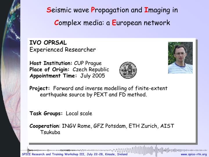
S eismic wave P ropagation and I maging in C omplex media: a E uropean network. IVO OPRSAL Experienced Researcher Host Institution: CUP Prague Place of Origin: Czech Republic Appointment Time: July 2005

E N D
Seismic wave Propagation and Imaging in Complex media: a European network • IVO OPRSAL • Experienced Researcher • Host Institution: CUP Prague • Place of Origin: Czech Republic • Appointment Time: July 2005 • Project: Forward and inverse modelling of finite-extent earthquake source by PEXT and FD method. • Task Groups: Local scale • Cooperation: INGV Rome, GFZ Potsdam, ETH Zurich, AIST Tsukuba
1D vs 3D strong ground motion hybrid FD modeling of topography effects at Augusta Raurica and Tricarico Ivo Opršal (1), Donat Fäh (2), Sandra Richwalski (3) Charles University, Prague, Swiss Seismological Service, ETH, Zurich, GFZ Potsdam
WhyHybridMethods? • Source + path + site effects are to be considered • “All-in-one” brute force methods (e.g. FD) are too expensive Two steps of the hybrid method: • source + path by DWN, ray, FD, or other 3D method • site by fine-grid FD
A recipe for the hybrid method Calculate 3D wavefield due to source and crustal part Solve 3D site model by FD using 1st step wave field, -> combined source - path-site effects The 2nd step is computed on a fraction of 1st step model size Full 3D excitation due to source and crustal propagation effects (step 1) can give more complete wave field than “plane wave excitation”
Augusta Raurica Ivo Oprsal (1), Donat Faeh (2) 1.7km x 1.9km, 0-12Hz Faculty of Mathematics and Physics, Charles University in Prague, Czech Republic Swiss Seismological Service, ETH Zurich
Motivation: -Augusta (founded at the same time as Basel, 44 BC)was a prosperous city during the first and second centuries AD.It was virtually destroyed by an invasion of the Alemanni tribes around 250 AD. It was the late phase and the end of the Middle Roman Imperial Period. -One important topic of the city’s history in this period concerns the hypothesis of an earthquake striking the city at some time in the middle of the third century. This idea was formulated on the basis of archaeological features but has so far not been fundamentally tested. The issue is addressed in an interdisciplinary approach by archaeologists and seismologists.
Motivation: -Augusta (founded at the same time as Basel, 44 BC)was a prosperous city during the first and second centuries AD.It was virtually destroyed by an invasion of the Alemanni tribes around 250 AD. It was the late phase and the end of the Middle Roman Imperial Period. -One important topic of the city’s history in this period concerns the hypothesis of an earthquake striking the city at some time in the middle of the third century. This idea was formulated on the basis of archaeological features but has so far not been fundamentally tested. The issue is addressed in an interdisciplinary approach by archaeologists and seismologists.
fluvial sediments (predominately gravels, Pleistocene, “Niederterrassenschotter”) Augusta Raurica structure EW vertical slice model [1,2] 150m • Keuper layers • - 500 and 600m/s (5-15m u. Quat. Base) • 1500 m/s – at contact with Muschelalk 20m Muschelkalk (limestones) 2400 m/s = geophysical bedrock Oberer Muschelkalk - Triassic carbonate sequences - 1800m/s - 2000m/s 1750m
Computational model - mu parameter 150m 1750m
Velocity wave filed 0-12Hz, animation 3 x slower than reality N
N Chosen sections of the computational model High PGV correlate with topographical sediments N
Spectral amplification Maxima are more scattered than for PGV PGV
known collapsed structures Augusta Raurica – spectral amplification, (vertical incidence)
1D (pseudo3D) modeling method • Matrix method for 1D layered media of (Mueller, 1985) is used to compute the 1D P-SV response for the repective S-wave (code Bartak and Zahradnik (1991)) • individual 1D structures in 195 x 213 points, are extracted from the 3D FD computational model by retrieving a vertical profile under each point. • The 1D computation is performed separately for every individual structure • This approach is understandably giving more information then a simple 1D model, however, it does not have a real 3D performance, hence 1D-pseudo-3D modeling. local 1D model 3D FD computational model N Number of 1D models: 213 (S-N)x195 (W-E) Bartak, V., Zahradnik, J., 1991. Program SITEF_MULT, version 1991, modified by Oprsal, I. for code sitefio.f90, 2004. Mueller, G., The reflectivity method: a tutorial. J. Geophys., 58, 153-174, 1985.
Augusta Raurica – spectral amplification 3D versus 1D 1D (pseudo 3D) 3D / 1D 3D
CONCLUSIONS: -Spectral-acceleration amplifications on topographical part of the city reach typically 5 (max>9) at band 4-6Hz for vertical incidence 3D response -The 1D (pseudo 3D) response shows up to 2.8 times lower spectral amplification than 3D FD response in the area of the old Augusta Raurica city. -High 3D/1D amplification performed for zones and multiple signals is bound to topographical sediments. -The 3D modelling so far supports the scenario of the city being destroyed due to an earthquake in ~250AD
Tricarico S.M. Richwalski(1,2), I. Oprsal (3), S. Parolai (1), M. Mucciarelli (4), R. Wang (1), M. R. Gallipoli (4,5) GFZ, Potsdam, Deutschland CEDIM, Karlsruhe , Deutschland Faculty of Mathematics and Physics, Charles University in Prague, Czech Republic DiSGG, University of Basilicata, Potenza, Italy MAA – CNR Tito Scalo (PZ), Italy
TRICARICO (604m x 604m, 0-12Hz) -The respective earthquake hazard is moderate to high according to the Italian official seismic classification (0.25 g for a return period of 475 years). -Damage was reported during the 1694, 1857, and 1980 earthquakes.
Tricarico geological profile -The town is situated on a calcarenite outcrop, which is underlain by argillaceous material with lower shear wave velocity, a common situation for many towns in this region (e.g. DiGiacomo et al, BSSA, 2005).
Spectral amplification West-East propagation vertical incidence Tricarico superficial Structure 604m x 604m Section 4 Section 4
Conclusions The 3D finite-difference (FD) hybrid approach computes the full 3D wave field due to source, path and site up to ‘engineering’ frequencies at reasonable computer demands. Pronounced topography at both sites reasonably contributes to 3D site effects leading to possible damages in the urban area in case of an earthquake. Compared to 1D-matrix response (for local 1D structures under each surface point), 3D methodology gives up~ 3x higher spectral amplification.
Outlook ーLocal 3D effects modelling for Rome ーModelling of complex combined processes source-path-> local non-linear behaviour - landslide, rockfall ーBenchmark