Download
1 / 49
490 likes | 614 Views
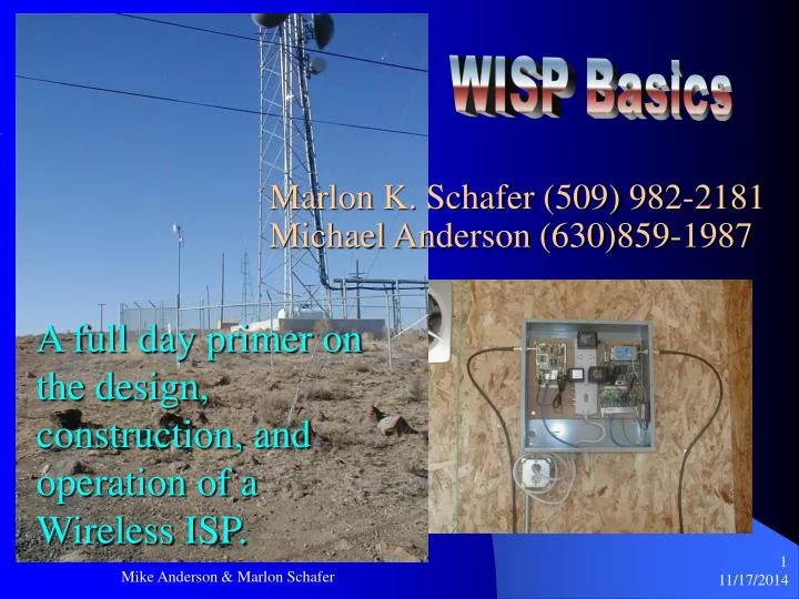
WISP Basics. Marlon K. Schafer (509) 982-2181 Michael Anderson (630)859-1987. A full day primer on the design, construction, and operation of a Wireless ISP. Introduction. WISP = Wireless Internet Service Provider

E N D
WISP Basics Marlon K. Schafer (509) 982-2181 Michael Anderson (630)859-1987 A full day primer on the design, construction, and operation of a Wireless ISP. Mike Anderson & Marlon Schafer
Introduction • WISP = Wireless Internet Service Provider • In this course you are going to learn the starting points and basics of becoming an profitable WISP. • We are going to assume you know nothing. If you have a question that we are not answering, please ask it. Mike Anderson & Marlon Schafer
Agenda • License Free Bands • Types of Unlicensed Radios • Basic system design • Definitions • Base Station (WPOP) Systems • Customer Premises Equipment (CPE) • Antennas • Calculations • Business plan • System design • Site Survey • Interference Issues • System examples • Cable Building/Connector sealing Mike Anderson & Marlon Schafer
Conventions 1 MHz = 1,000,000 Hz 1 GHz = 1,000 MHz 1 GHz = 1,000,000,000 Hz IE: 2400 MHz is the same as 2.4 GHz 928 MHz is the same as 928 MHz 5.8 GHz is the same as 5800 GHz Mike Anderson & Marlon Schafer
Conventions Continued Hz = Radio Spectrum Bits = Data K= 1,000 M = 1,000,000 G = 1,000,000,000 IE: 83.3 MHz is the amount of spectrum available in the 2.4 GHz band 11 MB/s is the over the air data rate of 802.11b (wi-fi) radios Mike Anderson & Marlon Schafer
License Free Bands ISM ISM: Industrial, Scientific, and Medical UNI-I (or UNII) Unlicensed National Information Infrastructure http://www.access.gpo.gov/nara/cfr/waisidx_01/47cfr15_01.html ISM = http://frwebgate.access.gpo.gov/cgi-bin/get-cfr.cgi?TITLE=47&PART=15&SECTION=247&YEAR=2001&TYPE=TEXT http://www.access.gpo.gov/nara/cfr/waisidx_01/47cfr18_01.html 902 to 928 MHz 2,400 to 2,483.5 MHz 5,725 to 5,850 HHz UNII = http://frwebgate.access.gpo.gov/cgi-bin/get-cfr.cgi?TITLE=47&PART=15&SECTION=407&YEAR=2001&TYPE=TEXT 5,150 to 5,250 MHz 5,250 to 5,350 MHz 5,725 to 5,825 MHz For some more info go to: http://www.odessaoffice.com/wireless/power_levels.html Mike Anderson & Marlon Schafer
900 MHz • 902 to 928 MHz • Data rates up to 3 megs • Non line of sight • Mostly abandoned but making a comeback • Unaffected by weather • Only a few manufacturers of gear • Expensive compared to 802.11b gear Mike Anderson & Marlon Schafer
2.4 GHz • 2,400 to 2,483.5 MHz • 83.5 MHz of spectrum • FHSS and DSSS • Speeds up to 22 Mbps common • Cheap Equipment • Not affected by weather • Needs Line of Sight • Unlicensed in Most Countries Mike Anderson & Marlon Schafer
5 GHz • 5,150 to 5,350/5,725 – 5,825/5,725-5,850(ISM) • Complicated power rules • Gobs of spectrum • Speeds up to 480 Mbps • Speeds up to 54 Mbps becoming common • Less congested than 2.4 GHz in most areas • Migrating from backhaul to distribution • Expensive gear • Mostly proprietary gear Mike Anderson & Marlon Schafer
Basic Wireless Diagram Mike Anderson & Marlon Schafer
Communications Methods • Two ways are common to all radios • Half duplex • Uses the same frequency to send and rec. • Uses different time slots • Commonly called TDD (time division duplexing) • Full duplex • Uses different frequencies to send and rec. • Uses the same time slots • Commonly called FDD (frequency division duplexing) Mike Anderson & Marlon Schafer
Vocabulary • http://www.odessaoffice.com/wireless/definitions.htm • There is not enough time to go through them all. • LOS: Line of sight • NLOS: Near/non LOS • BWA: broadband wireless access • PtMP: point-to-multipoint • PtP: Point-to-point • CPE: customer premises equipment • AP: access point • AU: access unit (same as above) • DS (or DSSS): direct sequence spread spectrum • FH (or FHSS): frequency hopping spread spectrum • RSSI: receive(r) signal strength index/indication • TDD: time division duplex • FDD: frequency division duplex • TDMA: time division multiple access • CSMA/CA: carrier sense multiple access/collision avoidance • CDMA: code division multiple access • ESSID: extended service set ID Mike Anderson & Marlon Schafer
Vocabulary • dB: The dB convention is an abbreviation for decibels. It is a mathematical expression showing the relationship between two values. • RF Power Level: RF power level at either transmitter output or receiver input is expressed in Watts. It can also be expressed in dBm. The relation between dBm and Watts can be expressed as follows: PdBm = 10 x Log Pmw. For example: 1 Watt = 1000 mW; PdBm = 10 x Log 1000 = 30 dBm 100 mW;PdBm = 10 x Log 100 = 20 dBm. For link budget calculations, the dBm convention is more convenient than the Watts convention. • Attenuation: Loss of power, expressed in dB. Attenuation is expressed in dB as follows:PdB = 10 x Log (Pout/Pin). For example: If, due to attenuation, half the power is lost (Pout/Pin = 2), attenuation in dB is 10 x Log (2) = 3dB. • Path Loss: Path loss is the loss of power of an RF signal travelling (propagating) through space. It is expressed in dB. Path loss depends on: 1. The distance between transmitting and receiving antennas. 2. Line of sight clearance between the receiving and transmitting antennas. 3. Antenna height. • Free Space Loss: Attenuation of the electromagnetic wave while propagating through space. This attenuation is calculated using the following formula: Free space loss = 32.4 + 20xLog F(MHz) + 20xLog R(Km) F is the RF frequency expressed in MHz. R is the distance between the transmitting and receiving antennas. At 2.4 Ghz, this formula is: 100+20xLog R(Km). Mike Anderson & Marlon Schafer
Calculations • No amp • Add radio output • Subtract cable/connector losses • Add antenna gain • With amp • Add radio output • Subtract cable/connector losses • Add amp gain • Subtract coax loss • Add antenna gain • For AGC amps use amp output instead of radio output and don’t count cable/connector loss Mike Anderson & Marlon Schafer
Effective Isotropic Radiated Power 17.5 dB radio – 1 dB misc. connectors – 2.3 dB coax loss + 24 dB antenna gain = 38.2 dB EIRP 30’ LMR 400 coax Mike Anderson & Marlon Schafer
Effective Isotropic Radiated Power 27 dB amp + 8 dB omni = 35 dB In this case, the amp has AGC (automatic gain control) so the radio output is not counted. Mike Anderson & Marlon Schafer
Free Space Loss • Also known as Path Loss • Amount of signal lost between the two ends of an RF link. • Calculated with the formula: Free space loss = 32.4 + 20xLog F(MHz) + 20xLog R(Km) F is the RF frequency expressed in MHz. R is the distance between the transmitting and receiving antennas. • At 2.4 Ghz, this formula is: 100+20xLog R(Km). Mike Anderson & Marlon Schafer
Coverage • Coverage is affected by a combination of EIRP and receiver sensitivity • Add 3 dB and you DOUBLE your wattage • Every 6 dB doubles or halves your coverage range 36 dB cell 4 x more area 30 dB cell Mike Anderson & Marlon Schafer
DSSS Signal Issues Notice how there are actually only 3 out of 11 channels that don’t significantly interfere with each other. Mike Anderson & Marlon Schafer
DSSS Signal Issues DSSS from a WiLan radio used for a video surveillance system shown on a spectrum analyzer. Mike Anderson & Marlon Schafer
802.11 Versions • 802.11 - 2 Mbps - 2.4 GHz • DSSS • FHSS • Infrared • 802.11b - 11 Mbps - 2.4 GHz • DSSS • 802.11a - 54 Mbps - UNII • OFDM • 802.11g - 11 and 54 Mbps - 2.4 GHz • DSSS • OFDM • There are several others but there’s no product for them at this time Mike Anderson & Marlon Schafer
Antennas • Antennas are also called “Intentional Radiators” by the FCC • Antennas focus energy • Focusing the energy causes a rise in energy in one direction equal to the loss of it in another. This is called “Gain” Mike Anderson & Marlon Schafer
Antennas • Antenna gain is measured at the highest spot on the coverage pattern • Beamwidth is measured at the point that the signal drops off by 3 dB • XPol (cross polarization) indicates how well an antenna isolates signals in the wrong polarization • F/B (front to back) ratio is an indication of how well an antenna squelches out signal coming in from behind it’s self Mike Anderson & Marlon Schafer
Antennas • When an antenna focuses it’s energy into a pattern it develops a “Beamwidth” • This would be an approximate pattern for a highish gain dish type antenna • Notice the large side lobes Mike Anderson & Marlon Schafer
Antennas • Here is a better picture of main beam vs. side lobes Mike Anderson & Marlon Schafer
Antennas • This is how antenna patterns are normally drawn Mike Anderson & Marlon Schafer
Antennas • Sample of a vertical pattern for a high gain (15 dB) omni • This is NOT the kind of coverage you will usually want • Notice how much more signal actually goes UP into lala land Mike Anderson & Marlon Schafer
Antennas • Not all antennas are created equal • Notice the much cleaner pattern from the panel antenna (bottom) vs. the grid antenna (top) • Pay special attention to the amount of signal that goes out the BACK of the grid Mike Anderson & Marlon Schafer
Antennas H-Pol grid V-Pol omni Panel H-Pol yagi Mike Anderson & Marlon Schafer
Antennas Rat Nest • All antennas on this tower are in use • It’s in South America • The 24 dB grids are all running P-Com back haul radios. As I recall there are 20+ of them! Mike Anderson & Marlon Schafer
Amplifiers Don't! • Design your system with NO amps as much as possible. • Don’t use amps at customer installs • Amps go at the antenna • For most amps try to keep coax loss down below 6 to 10 dB between the radio and the amp • Don’t over amp, as a rule the FCC HATES amps • There are basically two different types of amps: • AGC (automatic gain control) • Adjusts it’s output as needed to give a set dB total output • Generally easier to deploy as cable loss isn’t as much of an issue • Constant output • Gives the same boost to the signal at all times • Less complicated and sometimes less expensive • All amps add noise to the system • Usually about 3 dB • Amps do NOT add coverage to a system, power does that • Bigger amps do not always mean that a system will go further • For ptmp systems you are generally allowed 36 dB (4 watts) • A 9 dB omni with a 500mW (27 dB) will go NO further than a 12 dB omni with a 250 mW (24 dB) amp Mike Anderson & Marlon Schafer
Fresnel Zone • Pronounced Frunel • The area around a LASER beam tight radio link, a buffer zone if you will • Cigar shaped • Is all they way around an RF link but usually thought of as being on the bottom of it • Anything that’s in the RF path’s buffer zone is considered to be in the Fresnel Zone Mike Anderson & Marlon Schafer
Calculations • Receive signal Level • RSL=Tx Power-Tx cable loss+Tx andtenna gain-FSL+RX antenna gain-Rx cable loss • Free Space Loss • FSL = 20Log10(MHz)+20Log10(distance in miles)+36.6 • SOM (system operating margin) • SOM=Rx signal level-Rx sensitivity Mike Anderson & Marlon Schafer
Calculations • milliWatt to dBm • dBm=(10Log10(mW)) • 1 mW=0dBm • dBm to Watt • Watts=10((dBm-30)/10) • mW=10(dBm/10) Mike Anderson & Marlon Schafer
Business Plan • Realistic customer base in 12 to 18 months • Assume 20% of the population split among all broadband providers • What kind of customers do you want • How many live/work within your expected coverage • What kind of service will you give • What will they be willing to pay • What kind of equipment will your service require • How many wpops will you need to cover them • Both from an RF and from a BW stanpoint Mike Anderson & Marlon Schafer
Marketing Ideas • Local paper • Billboards • Radio • TV • Door to door • Word of mouth • Flyers at local businesses Mike Anderson & Marlon Schafer
WPOP Design • Choosing a site • Look before you leap • First do a visual sweep of the area • Can you see your customer base well? • Is there a better spot? • Are there others already up there? • Are there any other systems up there? This system is in Greece. The customer’s antennas are the two grids. He has to amp them to go 15 miles due to all of the noise in the area. He’d have been better off to use solid dish antennas, or better yet a different local. Mike Anderson & Marlon Schafer
WPOP Design • Look for causes of interference. • It could be your own • It could be from someone else • One of this person’s other towers was on a cell phone tower. It looked even worse than this. The red arrow is showing a DSSS backhaul, blue is ONE of the dead areas of the FHSS distribution system caused by another DSSS backhaul link on the same tower. Notice how little of the system is actually working. If this were a correctly designed and installed wpop the FHSS system would have filled in pretty evenly all the way across the display. Mike Anderson & Marlon Schafer
WPOP Design • Make sure that there are no high end radio systems in the same frequency range as you • This was from a Western Multiplex Lynx FDD system. Transmits one direction on one frequency and the other direction on another frequency • Very nice system • Unless it’s not yours….. The Blue arrow is from a 30 mile cell phone tower link. It’s 1 mile away and ¼ mile to the side of my site. The orange arrow is from the OTHER and of that link, 30 miles away. Mike Anderson & Marlon Schafer
WPOP Design • Try to locate your system where no one else is • Look for places that can see the most (notice that I didn’t say all) potential customers The arrow points to the NOC where the wireless backhaul is located. This is the view of downtown Odessa as seen from the 200’ hill where my main broadcast antenna is. The antenna is 20’ higher, on the peak of Herman’s second story roof. Mike Anderson & Marlon Schafer
WPOP Design • This would be a typical small WPOP broadcast setup • You can see the radio, pigail, dc injector, amp, coax, antenna and a mount for the side of a building/pole Mike Anderson & Marlon Schafer
WPOP Design Mike Anderson & Marlon Schafer
WPOP Design Mike Anderson & Marlon Schafer
WPOP Design Mike Anderson & Marlon Schafer
Customer Premisis Equipment Mike Anderson & Marlon Schafer
Customer Premisis Equipment Mike Anderson & Marlon Schafer
Tool Kits Mike Anderson & Marlon Schafer
Making Cables Mike Anderson & Marlon Schafer
Resources • www.isp-lists.com • www.wispcon.info • www.part-15.org • www.wcai.com • www.fcc.gov Mike Anderson & Marlon Schafer