Download
1 / 9
90 likes | 165 Views
Measurement of CNT Based Fibers and Cavities. Holly Tourtillott University of Missouri. Faculty Advisor: Dr. Uche Wejinya Graduate Student Advisor: Zhuxin Dong Department of Mechanical Engineering, University of Arkansas May 29, 2009. Outline. Carbon Nanotubes Objectives

E N D
Measurement of CNT Based Fibers and Cavities Holly Tourtillott University of Missouri • Faculty Advisor: Dr. Uche Wejinya Graduate Student Advisor: Zhuxin Dong Department of Mechanical Engineering, University of Arkansas May 29, 2009 Micro and Nano Systems Engineering Laboratory, University of Arkansas
Outline • Carbon Nanotubes • Objectives • Microelectrode Chip • Measurement of NanoCavities and Fiber Electrodes • Measurement Result • References Micro and Nano Systems Engineering Laboratory, University of Arkansas
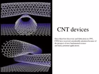
Carbon Nanotubes • Seamless hollow cylinder with diameter of approximately one to fifty nanometers • Can be basically divided into two kinds: Single walled and multi walled • Are the strongest and stiffest materials yet discovered in terms of tensile strength and elastic modulus respectively • Used in solar cells, electrical circuits, ultracapacitors, and often used as a vessel for transporting drugs into the body Micro and Nano Systems Engineering Laboratory, University of Arkansas
Objectives • Measurement of cavities and fibers on micro-electrode chip • Scan the entire electrode using the AFM tool • Measure the height of the fibers, depth of the cavities and diameters of both • Match the fibers into the cavities to fabricate microelectrodes and sensors Micro and Nano Systems Engineering Laboratory, University of Arkansas
Microelectrode Chip C1 C2 C3 C4 C5 C6 C7 C8 C9 C1 C9 A3 A5 A7 A2 A4 A8 A1 A6 A9 200 μm square A1 = Array 1 C1 = Contact Pad 1 Micro and Nano Systems Engineering Laboratory, University of Arkansas
Measurement of Nano Cavities and Fiber Electrodes Cavity Fiber 9 arrays under camera view to scan A 9×9µm area scanned in one array, cavities and fibers are found. A 3D topography image Micro and Nano Systems Engineering Laboratory, University of Arkansas
Measurement Result Micro and Nano Systems Engineering Laboratory, University of Arkansas
References -Microscope: Agilent 5500 ILM, Atomic Force Microscope -Website: http://en.wikipedia.org/wiki/Carbon_nanotubes -Book: Carbon Nanotube- Multifunctional Material, Edited by Prakash R. Somani and M. Umeno, Applied Science Innovations -Website: http://ieeeexplore.org/nanotubes Micro and Nano Systems Engineering Laboratory, University of Arkansas
Thank You! Any Questions? Micro and Nano Systems Engineering Laboratory, University of Arkansas