Download
1 / 28
280 likes | 379 Views
Injection into EMMA. Electron Model with Muon Applications. Electron Model with Many Applications. C. Johnstone, Fermilab NFMCC meeting Fermilab February 9, 2007. Global Ring Properties. ~18 m circumference; ~55 ns circulation time Fast kickers Ring Lattice Doublet lattice

E N D
Injection into EMMA Electron Model with Muon Applications Electron Model with Many Applications C. Johnstone, Fermilab NFMCC meeting Fermilab February 9, 2007
Global Ring Properties • ~18 m circumference; ~55 ns circulation time • Fast kickers • Ring Lattice • Doublet lattice • Short long straights, ~20 cm • Rf every other cell • Diagnostics • BPMs • OTRs • Single Wire Scanners
Orbit positions move as a function of energy Extraction energy – outside of ring Injection energy, inside of ring
Injection parameters Injection from outside of ring – total excursion from injection point 3 (offset of 20 MeV/c orbit) + 7 (extraction acceptance) + 3 (beam-stay-clear) + 5 (septum thickness) + 3 (beam-stay-clear) + 1 (injected beam size) = +22 mm. Injection from inside of ring – total excursion from injection point -11 (offset of 10 MeV/c orbit) - 7 (injection acceptance) - 3(beam-stay-clear) – 5 (septum thickness) – 3 (beam-stay-clear) -1 (injected beam size) = -30 mm. Excursion: Outside vs. Inside: 22 – (-11) = 33 mm vs. -30 – (-11)=19 mm The kicker strength will be significantly reduced if injection is performed from the inside of the ring simply due to the lower total excursion requirement.
The Simulation • The actual kicker strengths needed were modeled using the closed ring lattice with orbit offsets found using MAD and a defined reference orbit which corresponds to 19.0 MeV, or the energy of the central orbit that traverses the 0-field point of the horizontally-focusing quadrupole. • A horizontal, 10-cm long kicker centered in the 20 cm straight was varied until the needed offset was achieved at the septum by tracking backward from the kicker through the lattice. • The trajectory is towards the reference orbit at the exit of the septum, the offset and therefore the kicker strength was larger than that needed at the exit of the septum • With a phase advance of ~120 at injection, the offset at the septum is not optimal as in a 90 lattice. Further, the kicker strength is strong and the septum needs to be located in the straight consecutive to the kicker.
Injection, 10 MeV, closed orbit Plots of the closed injection-energy orbit traced backwards through a standard EMMA cell. The black line represents the offset of the 10 MeV beam relative to the reference trajectory established at 19.0 MeV and red is the angle of this orbit relative to this reference
Extraction, 20 MeV, closed orbit Plots of the final, or extraction-energy machine orbit traced backward through a standard EMMA cell.
Scaling As a function of momentum • Parallel orbits • Constant optical properties • Orbit change, r, linear vs. Linear Non-Scaling As a function of momentum • Nonparallel orbits • Varying optics • resonance crossing • Orbit change ~quadratic • Smaller aperture requirements • Simple magnets min
Optical layouts of FFAGs • Scaling and nonscaling lattices can have identical optical structures • FODO • Doublet • Triplet Rf drifts • The important difference is in the TOF vs. p, which is of particular importance for the linear non-scaling lattice: the FODO is 1.5 x (T1 + T2) as compared with the triplet (lower Timplies less phase slip, more turns for fixed, high frequency rf)
Momentum Compaction of Orbits • Momentum Compaction, • Measure of orbit similarity as a function of momentum (also isochronicity for relativistic beams) • Measure of the compactness of orbits - 0, aperture 0
Momentum compaction in scaling FFAGs • Scaling FFAGs: • Pathlength or TOF always increases with p
Momentum compaction in linear nonscaling FFAGs • Linear non-scaling FFAGs:
Cont…. F l • But, the transverse excursion cannot be ignored at low energy • Eventually this transverse correction overtakes the net decrease with low momentum and C turns around giving an approximate quadratic dependence of C and TOF.
What does this mean? • Scaling FFAG can have only 1 fixed point, or orbit with is synchronous with the rf (fixed points are “turning” points in the phase slip relative to the rf waveform) • 1 turning point implies the beam slips back and forth across the rf crest twice • Linear nonscaling FFAG can have 2 fixed points (or 1) • Beam can optimally cross the rf crest 3 times • By using two fixed points for maximal acceleration, the ratio of extraction energy can be ~3:2 for nonscaling vs. scaling FFAGs Fixed points
Electron Model - Non-scaling Demonstration of New Accelerator Physics Momentum Compaction Unprecedented compaction of momentum into a small aperture. Gutter Acceleration asynchronous acceleration within a rotation manifold outside the rf bucket. “Uncorrectable” Resonance Crossing Rapid crossing of many resonances including integer and ½ integer; multi-resonance crossings in a single turn Evolution of phase space Under resonance conditions and gutter acceleration Validate concept for muon acceleration Characterize and optimize the complex parameter space for rapid muon accelerators
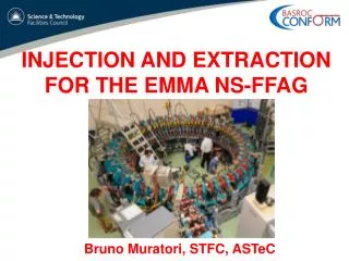
Electron Model - Construction – similar to the KEK ATF without straight sections (scaled down from 1.5 GeV to 20 MeV). Host: Daresbury Laboratory U.K. downstream of their 8-35 MeV Energy Recovery Linac Prototype (ERLP) of the 4th Generation Light Source (4GLS). 6m 6m
Radiofrequency system Where possible adopt designs already existing at the host laboratory. Adopt 1.3 GHz ELBE buncher cavity to be used at Daresbury 4GLS R=1M, Q=1.4104 1.3 GHz preferred over 3 GHz: reducing RF while magnet length is fixed, implies magnets become a smaller number of RF wavelengths. This implies smaller phase slip and more turns. 20 cm straight for installation Frequency variation of few 10-4 to investigate 1 or 2 fixed points operation. Adopt TESLA-style linear RF distribution scheme to reduce number of waveguides
Combined function magnet Specifications • Dipole component of 0.15 T • Slot length: 10 cm • Magnetic length: 7cm • Quad component of ~4T/m • Magnet spacing: 5 cm • Aperture (good field): 50 mm wide, 25 mm high • Field uniformity 1% at pole tip • Space for internal BPM • 1Hz operation or less • No cooling • No eddy current problems
Diagnostics • Diagnostic designs described here • BPMs • bunch train/single bunch operation • Turn by turn data • OTRs (Optical Transition Radiation) • Foils + detection • 108/bunch or lower for a bunch train • 109/bunch for single bunch operation – will require closer examination for 108/bunch, single bunch operation • Other diagnostics • Single Wire Scanners • orbits are non-overlapping, • step increment microns • Pepperpot • phase space measurements in extraction line
Electron Model - Demonstrates: Unprecedented compaction of momentum Asynchronous 2-fixed pt. gutter Acceleration Resonance Crossing Evolution of phase space and comparison with simulation Validate concept for muon acceleration
Electron Model - Hardware and Measurements: Magnetic components designed or under design; short: 5-6 cm and strengths appear technically reasonable • Full Complement of Diagnostics designed or available including • Large aperture BPMs, OTR foils and detectors • Single Wire Scanners, Pepperpots • Measure: • orbits, orbit stability, injection stability • probe injection phase space with a pencil beam • tolerances : field, injection, contributions of end fields • Evolution of phase space and comparison with simulation under different conditions of acceleration and resonance crossing • optimization and operational stability of accelerator conditions