Download
1 / 25
250 likes | 463 Views
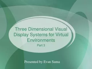
The Visual Display Transform for Virtual Reality. Cyrus Moon Computer Integrated Surgery II (600.446). Presentation Outline. Synopsis of Current Project Concepts introduced in the Reading VQS Representation Coordinate System Graph Object-to-Screen Transform

E N D
The Visual Display Transform for Virtual Reality Cyrus Moon Computer Integrated Surgery II (600.446)
Presentation Outline • Synopsis of Current Project • Concepts introduced in the Reading • VQS Representation • Coordinate System Graph • Object-to-Screen Transform • Relevancy of concepts to the current project
Current Project: Image/Video Overlay Image Overlay: -the merging of relevant computer generated information with the user’s actual view of the real world Video Overlay: -the merging of relevant computer generated information with display output from a video source
Relevant Concepts • Registration • Tracking in 3D real space • 3D modeling/rendering • Frame transformations
Background Reading Robinett Warren, Halloway Richard. The Visual Display Transformation for Virtual Reality. Technical Report TR94-031 (1994), Dept. of Computer Science, University of North Carolina at Chapel Hill.
VQS - Vector Quaternion Scalar Representation(for frame transformations) • Vector(v) (3 terms) displacement • Quaternion(q) (4 terms) rotation • Scalar(s) (1 term) uniform scaling [ (vx, vy, vz), (qx, qy,qz, qw), s ]
Advantages of VQS(over the Euler 4x4 homogeneous matrix) • Translation, rotation, and scaling components are separated • Renormalizing the rotation is simpler (since rotation and scaling are separate) • Uniform scaling in the virtual world a useful operation • Quaternions a better method of manipulating 3D rotations than Euler rotations
Advantages of the Quaternion (over the Euler 3x3 Rotation Matrix) • Fewer components (4 instead of 9); fewer redundant parameters • More elegant, numerically robust • Explicit representation of the angle and axis of rotation • Allows easy interpolation between two orientations
The Quaternion [(qx, qy, qz), qw] • (qx, qy, qz) axis of rotation • qw angle of rotation: • qw takes values from –1 to 1
Quaternion Math Addition: Multiplication: Multiplication by Scalar:
Quaternion Math (cont’d) Taking the norm: Normalization: Inversion: Interpolation:
Using Quaternions • Rotation of a vector p by quaternion q: pnew = q*p*q-1 -the vector p is treated as a quaternion w/ 0 as the 4th (scalar) term -the result will always have a 4th term of 0, as well
VQS Math Conversion to 4x4 Matrix: [v,q,s] = Mtranslate * Mrotate * Mscale =
Using VQS Transforms • Transformation of a vector (p) with VQS: p’ = [v, q, s]*p = s(q*p*q-1) + v • Composition of two VQS transforms: TA_B*TB_C = [vA_B,qA_B,sA_B]*[vB_C,qB_C,sB_C] = [(sA_B*(qA_B*vB_C*qA_B)-1) + vA_B, qA_B*qB_C, sA_B*sB_C] • Inverse of a VQS Transform: TA_B-1 = [vA_B, qA_B, sA_B]-1 = [1/sA_B*(qA_B-1*(-vA_B)*qA_B), qA_B-1, 1/sA_B]
The Coordinate System Graph Robinett & Halloway
The Coordinate System Graph • Representation: • Each Node represents a coordinate system • Each line represents some kind of independent transformation • Properties: • Connected: each node is connected with every other node • Acyclic: there is only one pathway between any two given nodes
Transformations • Independent: characterized by being independent variables within the software • Measured by tracker • Constant (rigid) • Dependent: calculated from independent transforms The Coordinate System Graph: -intuitively organizes all independent transforms and coordinate systems; easily expandable -allows easy calculation of any dependent transform present within the VR system
The Object-to-Screen Transform TS_O = TS_US * TUS_N * TN_E * TE_H * TH_HS * THS_TB * TTB_R * TR_W * TW_O -TB_A is defined as the transformation from frame A to B S = Screen HS = Head Sensor US = Undistorted Screen TB = Tracker Base N = Normalized R = Room E = Eye W = World H = Head O = Object
VQS Transforms • TW_O: World_Object – object in the virtual world. • v - position • q - orientation • s - size • TR_W:Room_World – the user position in the virtual world • v - position • q - tilt of the world • s - user's size (shrinking or expanding of the world) • TTB_R:TrackerBase_Room – position of tracker base (stored in calibration file) • s - must always be one (both cs’s in real-space) • Pre-calculated
VQS Transforms (cont’d) • THS_TB: HeadSensor_TrackerBase – inverse of the head position and orientation read from tracker • s = 1 • TTH_HS:Head_HeadSensor – position and orientation of the HMD sensor w/ respect to the head (center of the eyes) • s = 1 • Pre-calculated • TE_H:Eye_Head – position/orientation of head coordinate system w/ respect to each eye • v – different for each user (though a default value can be used • q – dependent on orientation of HMD displays • s = 1 • Pre-calculated
TEye_Head Robinett & Halloway
Non-VQS Transforms • TN_E: Normalized_Eye – perspective projection, normalization • Three to two dimensions (projection of world onto viewing plane) • TUS_N:UndistortedScreen_Normalized– conversion to pixel coordinates • Simple scaling process • TS_US:Screen_UndistortedScreen – correction of image distortion
Applicable Concepts • VQS Representation • Tracker Data Transform calculations • Registration Transforms (non-deformable objects) • Elimination of the possibility of warping • Coordinate System Graph • Other concepts discussed in the individual transforms • Example: perspective transform
Coordinate Graph (Video Overlay) World (Tracker) Camera Patient markers Lens Model (from Imaging) . . . . . . . . Tool 1 Tool k Screen
Coordinate Graph (Image Overlay) World (Tracker) Screen Patient markers Silvered Glass Virtual Projection Plane Model (from Imaging) Head . . . . . . . . Tool 1 Tool k