Download
1 / 96
1.02k likes | 2.1k Views
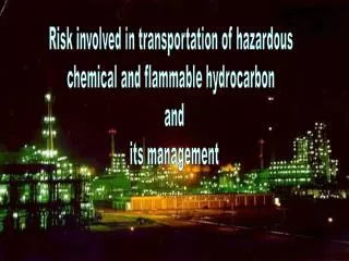
HAZARDOUS AREA CLASSIFICATION & SELECTION OF ELECTRICAL EQUIPMENT FOR FLAMMABLE ATMOSPHERES. Cholamandalam MS Risk Services Ltd, Chennai, India. www.cholarisk.com. Hydrocarbon Risks. OISD Accident compilation (1996-1999):

E N D
HAZARDOUS AREA CLASSIFICATION&SELECTION OF ELECTRICAL EQUIPMENT FOR FLAMMABLE ATMOSPHERES Cholamandalam MS Risk Services Ltd, Chennai, India www.cholarisk.com
Hydrocarbon Risks • OISD Accident compilation (1996-1999): • Out of the total 71 accidents (5 lakh property loss/fatality/loss of 500MH/led to plant SD ), 66% were fire accidents • 47% accidents happened during operational jobs • Causes of accidents: • 71% human error • 11% Failure of plant • 18% Presence of ignition source Is the above ‘accident cause’ grouping correct?
Hazardous Areas-Definitions • Petroleum Rules, 1976 • An area shall be deemed to be a hazardous area, where: • petroleum having FP below 65 deg C or any inflammable gas or vapour in concentration capable of ignition is likely to be present • petroleum or any inflammable liquid having FP above is likely to be refined, blended or stored at or above its FP • IS 5572 • Hazardous area is an area in which an explosive gas atmosphere is present, or likely to be present, in quantities such as to require special precautions for the construction, installation and use of electrical apparatus.
COAL MININING SAFETY & CRUDE WAYS OF DETECTING METHANE GAS!! • In the 1700's, certain gases or the lack of oxygen were detected with various hit and miss types of detection. The candles on miners caps, or if carried by the miner, would either go out from the lack of oxygen or the flame would get larger with a different coloring of the flame if certain gases were in the area. • Of course, in some instances these open flames caused fires or explosions. By 1815, the Davy's Safety Lamp came into use in the mines. This certainly changed the way for miners to check for certain gases. • They took these canaries in small cages with them down the coal mines where they worked. The canaries were the miners alarm signal to show them when the coal-gas levels got too high. The canary stopped singing and was most likely to be laid feet up on the bottom of the cage, poisoned by the mine gas.
Why Area Classification? • HAC is a method of analyzing and classifying the environment where explosive gas atmospheres may occur to allow the proper selection of electrical apparatus to be installed in that environment. • Ignition sources not considered • ESD • Sparks • Lightning • Flames/Fires • Hot surfaces • IS 5572 • HAs are classified in zones based on the frequency of the appearance and the duration of an explosive gas atmosphere.
Why Zoning? • Leak Potential & Presence of Ignition Sources • Hazardous properties of hydrocarbons • Safe selection (& optimization) of Electrical Equipment
AREA CLASSIFICATION • How many Zones as per Indian standards? • European & American classifications (Zones and Divisions) • Why not ‘blanket’ zoning? • Is the 4th Zone really a ‘safe’ zone? • Who should do HAC-Electrical or Process Engineer?
HAC as per IS 5572 is not applicable for: • Mining applications • Explosive manufacturing • Areas where ignitable dusts & fibers are present • Catastrophic failures • Ignition sources other than electrical apparatus
Zone 0 -Typical areas (Continous grade) • Vapour space above: • closed process vessels, • storage tanks • closed containers, • areas containing open tanks of volatile, flammable liquid
How to identify Zone 1 areas (IS 5572) ? (Primary grade) • Flammable gas or vapour concentration is likely to exist in the air under normal operating conditions • Flammable atmospheric concentration is likely to occur frequently because of maintenance, repairs or leakage • Flammable liquid or vapour piping system (containing valves, meters, or screwed or flanged fittings) is in an inadequately ventilated area • The area below the surrounding elevation or grade is such that flamamble liquids or vapours may accumulate therein
Zone 1 -Typical areas • Imperfectly fitting peripheral seals on floating roof tanks • Inadequately ventilated pump rooms for flammable gas or for volatile, flammable liquids • Oily waste water sewer / basins • Loading / unloading gantries of hazardous products
Typical Zone 2 areas (IS 5572) ?(Secondary grade) • The system handling flammable liquid or vapour is in an adequately ventilated area and is so designed and operated that the explosive or ignitable liquids, Vapours or gases will normally be confined within closed containers or closed systems from which they can escape only during abnormal conditions such as accidental release of a gasket or packing • The flammable vapours can be conducted to the location as through trenches, pipes or ducts • Locations adjacent to Zone 1 areas • Pressurized rooms where flammable gas / vapour can enter in the case of failure of positive mechanical ventilation
Safe Areas -Typical areas The following locations are considered safe from the point of view of electrical installation: • Areas where the piping system is without valves, fittings, flanges or similar appurtenances • Areas where flammable liquids or vapours are transported only in suitable containers or vessels • Areas where permanent ignition sources area present like area where combustion gases are present, for example flare pits, tips, other open flames 7 hot surfaces • DG shed room / shed having adequate ventillation • GT installation meeting the ventilation (12 ACPH) , pressurization (0.5 mbar )and flange (not more than one pair of flanges inside the turbine room) requirements
HAC- Comparison • North America (NFPA / API/ NFPA 70E or NEC) • Hazardous Areas: • Division I- Z0 + Z1 • Division II- Z2 • Hazardous Locations • Class I-Flammable Gases / Vapour • Class II- Combustible dust • Class III- Combustible fibres or flyings • Gas / vapour grouping • A, B, C, D, E, F & G • Japan • Hazardous Areas • Classes 1, 2 & 3 • Gas / vapour groups • G1, G2, G3, G4, G5 & G6
A FEW RELEVANT DEFENITIONS • Flash Point - A, B, C • Ignition Temperature • Explosive Limits (based on MIE) • LEL • UEL
HAZARDOUS AREA CLASSIFICATION-Guidelines Factors to be considered (IS 5572) • Vapour / Gas Density • Effect of Air Current • Identification of leak scenarios
GENERAL CONSIDERATIONS • In the absence of walls, enclosures, etc. & air currents, vapour/gas dispersion will depend on density & velocity. Denser gas/vapour will disperse downward and outward, lighter gases upward & outward.HA for a single leak source would be a circle. • Vapours / gas released(high density releases) at or near ground level, will be found below ground, thus altering the shape of HA.
EFFECT OF AIR CURRENT • Winds alter the shapes of hazardous areas • A mild breeze may extend the HA and a strong wind could dilute the flammable concentration,making it non-hazardous • But what are logically to be considered are the most unfavourable conditions
HEAVIER-THAN-AIR GASES & VAPOURS • Open -Air Situations (freely ventilated Process Areas) • Figures 1 ,2) • Figures 3 & 4 • In case of petroleum pipelines (where well-maintained valves, fittings, and meters and in well-ventilated areas or in a pit), Zone 2 A/G shall be 4m in all directions, from the potential leak source. Pit will be considered as Zone 1. • Zone 1 (unless separated by a fire wall) Zones 1 or 2
LIGHTER-THAN-AIR GASES & VAPOURS • Vapour density of 0.75 is considered as the boundary between lighter and heavier gases / vapours as a safety measure HA of a leak source located in air 4.5 m Source of hazard 8.0 m R 4.5 m H<4.5m Zone 2
How to classify areas? • Mark in elevation and plan drawings • Separate identification (hatching) for various zones • Zone 0 • Zone 1 • Zone 2 • Frequency of HAC?
An experienced process engineer’s judgement in visualizing leak scenarios and classifying hazardous areas is the most CRUCIAL factor in the HAC exercise
API RP 500- HAC Guidelines • Adequacy of ventilation • Accident record of the plant / business group / industry sector/maintenance standard adopted in the plant • Sound judgement & Experience of the engineer who carries out HAC
AREA CLASSIFICATION AS A TOOL FOR RISK ASSESSMENTA LOGICAL APPROACH • Perceived Limitations on the present HAC approach: • Ignition sources not considered • Reduction of zone areas & relaxation of zone designations not considered • Blinkers -On Approach , High cost, blanket zoning, narrow & easy approach or in short, the full potential of HAC is not utilized at present
AREA CLASSIFICATION AS A TOOL FOR RISK ASSESSMENT • EXTENDING HAC PROCEDURE • Additional steps • After applying the present HAC procedure, assess all ignition sources • Assess the grade of release using HAC-based risk assessment matrix • Assessing the ventilation & evaporation aspects of the chemicals considered • Applying the new HAC procedure
AREA CLASSIFICATION AS A TOOL FOR RISK ASSESSMENT CONCLUSION • A logical extension of the present HAC methodology & not a radical approach • New European legislation, ATEX 118a Directive will be on similar lines • The new focussed & practical HAC approach will make HAC exercise more cost-effective • A SAFE APPROACH?
COMPARISON OF ZONES & DIVISIONS Classified area Estimated % (Divisions) Time that haz. gases are present in ignitable Estimated % (Z) <2% Z0 Continuously Normally present Occasionally in normal operations Not normally present <5% D1 >60% Z1 Z2 <40% >95% D2
PERCENTAGE OF CLASSIFIED AREAS C L A S S I F I E D A R E A S Z2 Z 1 Z0 O 10 20 30 40 50 60 70 80 90 100
HAC-RELEVANT INTERNATIONAL STANDARDS • API RP 500- Area Classification of Petroleum Installations • IEC 79-10 :1995 -Electrical Apparatus for Explosive Gas Atmospheres, part 10 Classification of hazardous areas • IP Part 15, 1990- Area Classification Code for Petroleum Installations • BS EN 60079-10, : 1996 -Electrical Apparatus for Explosive Gas Atmospheres, part 10 Classification of hazardous areas • BS 5345, 1983-Selection, installation and maintenance of electrical apparatus for use in potentially explosive atmospheres (other than mining applications or explosive manufacturing), part 2, Recommendations for particular industrial situations
USEFUL REFERENCE BOOKS ON HAC • Classification of Hazardous Locations,I.Chem. E. Cox, A.W., Lees, F.P. and Ang, M.L, 1990 • IP Model Code of Safe Practice, 1990, Part 15, Area Classification Code for Petroleum Installations • NFPA 69, 1992, Explosion Prevention Systems • ICI/RoSPA, 1972, ICI Electrical Installations Code • NFPA 325M, Properties of Flammable Liquids, gases and solids • Electrical Safety in Hazardous Locations, William Calder & Ernest C. Magison
SELECTION OF ELECTRICAL EQUIPMENT IN HAZARDOUS AREAS • How to select equipment for various zones? • Selection Criteria • Gas Grouping (based on ignition energy) • Temperature Classification • Classified Zones
TEMPERATURE CLASSIFICATION Max. Surface Temperature (Deg. C) T Class T1 450 T2 300 T3 200 T4 135 T5 100 T6 85
GAS GROUP CLASSIFICATION (based on MESG & MIE) • Gas group I • Methane • Gas group II A • Ammonia, CO, Propane, Butane, Benzene, Acetone, Methanol • Gas group II B • Butadiene, Ethylene, Ethylene Oxide, Diethyl Ether • Gas group II C • Hydrogen Which is the most hazardous group ?
GAS GROUP & TEMPERATURE CLASSIFICATION-VARIOUS GASES/VAPOURS (IS 13408 Part I)
GAS GROUP & TEMPERATURE CLASSIFICATION-VARIOUS GASES/VAPOURS Gas Representative Gas Ignition Energy Group (mj) I Methane 280 II A Propane 260 IIB Ethylene 95 IIC Hydrogen 18
RECOMMENDED PROTECTION METHODS FOR ZONE O No electrical equipment should be allowed. When this is not practicable, Ex ‘ i ‘ (ia or ib) apparatus or circuits to be used • No transformers, motors, lights, switch gear or control gear
RECOMMENDED PROTECTION METHODS FOR ZONE 1 Motors- Ex d, Ex p Transformers & Capacitors - Ex d Control & Instrument Transformers - Ex i Lighting Fitting - Ex d Switch Gear & Control Gear - Ex d Communication/ Telephone equipment/Meters - Ex i Portable Hand Lamps- Ex i *Ex o, Ex q type equipment are also allowed for use as per IS 5571
RECOMMENDED PROTECTION METHODS FOR ZONE 2 Motors- Ex d, Ex p, Ex n, Ex e, Transformers & Capacitors - Ex d, Ex p (auxiliary devices to be located in pressurized room/hermetically sealed / intrinsically safe) Control & Instrument Transformers - Ex i Lighting Fitting - Ex d, Ex e, Ex n Switch Gear & Control Gear - Ex d, Ex o, Ex Communication/ Telephone equipment/Meters - Ex i Portable Hand Lamps- Ex i * Minimum IP 55 (for UN-insulated parts) and IP 44 (for insulated parts) if Ex e protection is used for outdoor applications
EXPLOSION-PROTECTION METHODS / EQUIPMENT -Popular types • Flameproof (EX d) • Increased Safety (Ex e ) • Non-Sparking (Ex n ) • Pressurization (Ex p ) • Intrinsically Safe (Ex i )
OTHER TYPES OF EXPLOSION PROTECTION- Not so popular types • Powder filled Ex ‘q’ type • Oil immersed Ex ‘o’ type • Special Ex ‘s’ type
EX ‘d’ Type FLAMEPROOF EQUIPMENT Definition as per IS 2148: US- Explosion-Proof, UK- Flame-Proof, GERMANY - Pressure-Proof A type of protection in which the parts can ignite an explosive atmosphere are to be placed in an enclosure, which can withstand the pressure developed during internal explosion of an explosive mixture, and which prevents the transmission of the explosion to the explosive atmosphere surrounding the enclosure FLAMEPROOF EQUIPMENT- A MISNOMER?
FLAMPROOF (EXPLOSION-PROOF) PROTECTION (Ex ‘d’) • Assumptions based in IS 2148 are: • Flammable gases / vapours, if present in atmosphere will enter the enclosure • The apparatus will be selected, installed, operated and maintained within the acceptable ratings. The maintenance and use of FLP equipment shall be so that its safety will not be impaired, is the responsibility of the user • The electric circuit of the FLP equipment will have all required protection devices • Sparking which will ignite a flammable gas or vapour, may occur at any part of the equipment contained in the enclosure in normal operation due to an internal fault due to insulation failure, etc.
FLAMPROOF (EXPLOSION-PROOF) PROTECTION (Ex ‘d’) • FLAME PATH - Width of Joint • Minimum • GAP - Diametrical Clearance • Maximum
FLAMPROOF (EXPLOSION-PROOF) PROTECTION (Ex ‘d’) • Maximum gaps and flame path for gas groups depends on ignition energies of the gas / vapour and the volume of the enclosure • For example, for IIB gas group, for 100 Cubic cm volume, for flanged joints: • Flame Path - 6 mm • Maximum Gap - 0.3 mm • For II C Hydrogen, 100 cubic cm volume, for flanged joints: • Flame path - 9.5 mm • Maximum Gap - 0.1 mm
FLAMEPROOF EQUIPMENT- CONSTRUCTIONAL REQUIREMENTS • USE OF APPROVED MATERIAL WITHOUT THE USE OF INCENDIVE FRICTIONAL SPARKING • EQUIPMENT SHOULD WITHSTAND ROUGH USAGE • EQUIPMENT SHALL BE ADEQUATELY STRONG TO WITHSTAND ALL REQUIRED TESTS • THE EFFECTIVE THREADED METAL TO METAL JOINTS SHALL HAVE A MINIMUM OF 5 FULL UNINTERRUPTED ENGAGED THREADS & A MINIMUM EFFECTIVE UNINTERRUPTED DIRECT AXIAL LENGTH OF THREADED ENGAGEMENT OF 9 mm • THERE SHALL BE NO INTENTIONAL GAP BETWEEN JOINT SURFACES • NO PACKING MATERIAL SHALL BE USED BETWEEN OPPOSED SURFACES TO FORM A FLAMEPROOF JOINT • IF COMPRESSIBLE PACKING MATERIAL OR A GASKET IS NECESSARY TO SEAL A JOINT (eg. IP) THE PACKING SHALL BE APPLIED AS A SUPPLMENT TO, BUT SHALL NOT BE INCLUDED IN THE FLAMEPROOF JOINT • ANY DISPLACEMENT, DAMAGE, INTEGRATION OR OMISSION OF THE PACKING SHALL NOT RESULT IN THE FLAMPROOF NATURE OF THE JOINT BEING ADVERSELY