Download
1 / 30
360 likes | 661 Views
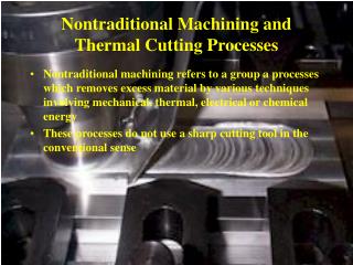
Machines & Machining Issues. Material Removal Process. Mechanical Machining. Turning. Milling. Drilling. Grinding. All hard materials. Machining DOF (Degrees of Freedom). DOF - # of independently controllable axes of motion-- excluding spindle

E N D
Material Removal Process Mechanical Machining Turning Milling Drilling Grinding All hard materials
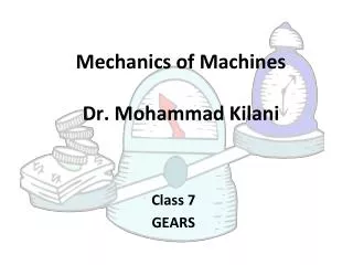
Machining DOF (Degrees of Freedom) • DOF- # of independently controllable axes of motion-- excluding spindle • rotation or tool translation responsible for cutting. • 1 DOF- Drill Press • 2 DOF- Lathe • 3 DOF- 3 independent axis motions between tool & table • Can use a ball end mill w/ 3 axis machine- for smoothest contour • Following a true 3-D contour requires a minimum of 3 DOF • 2 1/2 DOF- 3 independent axes, but can only move 2 at a time • > 3 DOF- Generally allows rotation of spindle wrist or table • Helps keep tool normal to workpiece/ fewer separate fixtures • 5 DOF- Minimum to follow any normal at any point
Turning Operations • Turning (Performed on lathe) • Part is moving and tool is stationary. • Used to make parts of round cross section • Screws, shafts, pistons.... • Number of various lathe operations • Turning, facing, boring, drilling, parting, threading
Lathe Components Machine Components (Main items) Bed: Supports all other machine parts Carriage: Slides along the machine ways • Head stock: Power train of system (spindle included) • Tail Stock: Fixes piece at end opposite to the head stock • Swing: Maximum diameter of the machinable piece • Lead screw: controls the feed per revolution with a great deal of precision
Spindle Speed Selector Headstock Spindle Ways Cross Slide Tool Post Carriage (saddle) Center Tailstock quill Feed change gear box Tailstock Compound Rest & Slide (swivels) Apron Bed Lead Screw Feed Rod Lathe Ref: Fig. 8.52, Kalpakjian. Manufacturing Processes for Engineering Materials 2nd Ed, Addison-Wesley 1991.
Lathe Tools Lathe tools • Left handed • Right handed • Threading • Boring • Groove • Parting (Cut-Off )
Lathe Operations Ref: Fig. 8.51, Kalpakjian. Manufacturing Processes for Engineering Materials 2nd Ed, Addison-Wesley 1991.
Cutting Speeds Typical Lathe Cutting Speeds • Nominally 30 - 800 ft./min. • Roughing cuts • Depth of cut greater then .02 in • Feed speed of .008 - .08 in/rev. • Finishing Cuts • Lower than roughing cuts.
Milling Types of Milling Machines • Horizontal Milling Machine • Vertical Milling Machine
Mill Cutting Direction Cutting direction- Depending on the orientation of the workpiece feed w.r.t. the rotation of the cutting tool. • Conventional (Up) Milling-Maximum thickness of chip at end of cut Ref: Figure J-48, Kibbe ,et al. Machine Tool Practices 5th Ed, Prentice Hall,1995. • Climb (Down) Milling- Maximum thickness of chip at start of cut. Ref: Figure J-48, Kibbe ,et al. Machine Tool Practices 5th Ed, Prentice Hall,1995.
Vertical Knee Milling Machine Base and Column- support structure Knee- Connected to slide on column- can move up and down Saddle- Engages slide on top of knee- can be moved in and out. Table- Engages slide atop of saddle- moved lengthwise. Holds workpiece. Ram- Engages swiveling slide atop column. Toolhead- Attached to end of ram, contains motor and quill. Quill- Non rotating, but contains rotating spindle. Can be moved up and down. Ref: Figure 8.69, Kalpakjian. Manufacturing Processes for Engineering Materials 2nd Ed, Addison-Wesley 1991. Ref: Kibbe ,et al. Machine Tool Practices 5th Ed, Prentice Hall,1995, p 550-551
Vertical Milling Machine • Flexible • Versatile • Newer machines – more DOF
Bed Mill • Similar to vertical knee milling machines • Less versatile than knee mill • No knee - Bed does not move up and down • Vertical motion possible in head only • Controllable range of motion of head larger than in knee mill (total range of motion less) • Bed mill stiffer than knee mill
Vertical Milling Applications Collet Ref: Process Selection, KG Swift and JD Booker, p.98.
Horizontal Milling Machine COMPONENTS Base & Column Knee Saddle Table Spindle Overarm & Arbor Support Ref: Figure 8.68, Kalpakjian. Manufacturing Processes for Engineering Materials 2nd Ed, Addison-Wesley 1991.
Types Horizontal Milling Operations • Slab-Axis of cutter // • to workpiece surface • Face- Axis of rotation | • to workpiece surface Figure 8.63b, Kalpakjian. Manufacturing Processes for Engineering Materials 2nd Ed, Addison-Wesley 1991. Figure 8.63a, Kalpakjian. Manufacturing Processes for Engineering Materials 2nd Ed, Addison-Wesley 1991. • Side- Axis of cutter // • to workpiece surface Figure 8.67c, Kalpakjian. Manufacturing Processes for Engineering Materials 2nd Ed, Addison-Wesley 1991.
Drilling Any component requiring cylindrical holes. Engine Blocks, Machine Components Ref: Process Selection, KG Swift and JD Booker, p.104.
Grinding and Abrasive Processes • Abrasive Processes- Generally slower (more expensive) than other traditional machining processes. Used on very hard materials, and can achieve HIGH (virtually unmatched) levels of precision and finish. • Grinding • Deburring • Honing • Polishing • Lapping • Superfinishing
Grinding Machines Pedestal Grinder Surface Grinder Type I- Horizontal spindle w/ reciprocating table Type II- Horizontal spindle w/ rotary table Type III- Vertical spindle, table either reciprocates or rotates (blanchard) Cylindrical Grinder Center-type Roll-type- workpiece in bearings rather than on centers Centerless Grinder- workpiece supported on rest blade, grinding wheel on one side, regulating wheel on the other Internal Cylindrical Grinder Tool Cutting Grinders Specialty Grinders Form Grinders and Generating Types
Surface Grinders Type I Type II Type III Reciprocating Table Rotating Table Ref: Figures N-1, N-3,N-4, & N-5, Kibbe ,et al. Machine Tool Practices 5th Ed, Prentice Hall,1995.
Cylindrical Grinders Centerless Type Center/Roll Type Ref: Figures N-8, N-17, N-18, Kibbe ,et al. Machine Tool Practices 5th Ed, Prentice Hall,1995.
( ) |a| + |b| + |c| + |d| + … n Ra= Surface Roughness Surface roughness is generally described with 1 of 2 methods Ra- Arithmetic Mean Value- the average of the absolute values of the deviations from the center line of the surface Rq (formerly RMS)- Root Mean Squared-
Roughness Units Both generally given in micrometers (microns) or microinches • 1 Micrometer = 1mm = 1 micron = 10-6 meters • 1 Microinch = 1min= 10-6 inches • 1min = 0.025 mm • 1mm = 40 min • Human hair ~ 40 mm
Typical Arithmetic Average Roughness Ref: Fig. 8.35, Kalpakjian. Manufacturing Processes for Engineering Materials 2nd Ed, Addison-Wesley 1991.
Summary • Four types of mechanical removal processes • Turning • Milling • Drilling • Grinding • Finish of workpiece
Credits • This module is intended as a supplement to design classes in mechanical engineering. It was developed at The Ohio State University under the NSF sponsored Gateway Coalition (grant EEC-9109794). Contributing members include: • Gary Kinzel …………………………………….. Project supervisor • Chris Hubert and Alan Bonifas ..……………... Primary authors • Phuong Pham and Matt Detrick ……….…….. Module revisions • L. Pham ……………………………………..….. Audio voice • References: • Kalpakjian, Manufacturing Processes for Engineering Materials2nd Ed, Addison-Wesley 1991 • Kibbe ,et al. Machine Tool Practices5th Ed, Prentice Hall,1995 • Swift, KG and JD Booker, Process Selection, Arnold/John Wiley& Sons Inc., New York, 1997
Disclaimer This information is provided “as is” for general educational purposes; it can change over time and should be interpreted with regards to this particular circumstance. While much effort is made to provide complete information, Ohio State University and Gateway do not guarantee the accuracy and reliability of any information contained or displayed in the presentation. We disclaim any warranty, expressed or implied, including the warranties of fitness for a particular purpose. We do not assume any legal liability or responsibility for the accuracy, completeness, reliability, timeliness or usefulness of any information, or processes disclosed. Nor will Ohio State University or Gateway be held liable for any improper or incorrect use of the information described and/or contain herein and assumes no responsibility for anyone’s use of the information. Reference to any specific commercial product, process, or service by trade name, trademark, manufacture, or otherwise does not necessarily constitute or imply its endorsement.