Download
1 / 36
360 likes | 504 Views
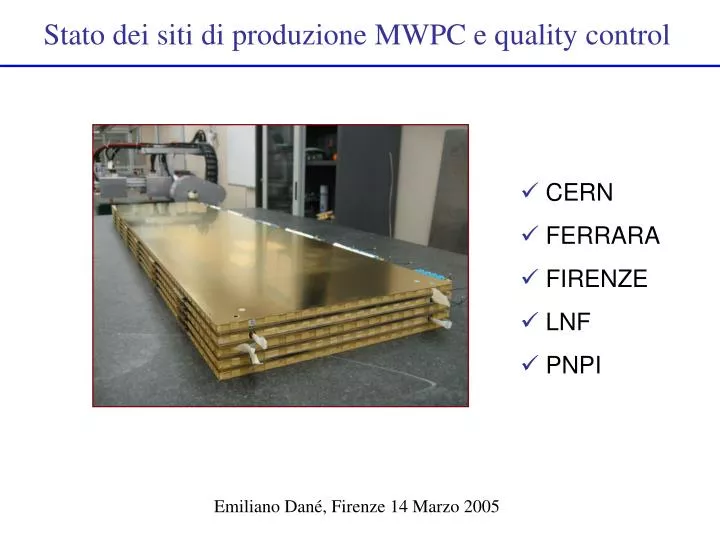
Stato dei siti di produzione MWPC e quality control. CERN FERRARA FIRENZE LNF PNPI. Emiliano Dané, Firenze 14 Marzo 2005. Pianificazione della produzione di MWPC. PNPI 600 chambers (M2/3/4-R4) LNF 248 chambers (M3/M5-R3, M5-R4, M1 -R3/ 4 )

E N D
Stato dei siti di produzione MWPC e quality control • CERN • FERRARA • FIRENZE • LNF • PNPI Emiliano Dané, Firenze 14 Marzo 2005
Pianificazione della produzione di MWPC PNPI 600 chambers (M2/3/4-R4) LNF 248 chambers (M3/M5-R3, M5-R4, M1-R3/4) Ferrara 246 chambers (M2/4-R3, M4/5-R2, M1R4) Firenze 218 chambers (M5R4 and M1R4) CERN 134 chambers (M2/3-R1/2, M4/5-R1, M1R2) Total 1446 (circa il 6% di spares)
Status of production at CERN • M3R1: needed=12 (+2 spare). Total chambers built=16. • Completely tested and all GOOD • M3R2: needed=24 (+2 spare). • Complete • 25 tested for leaks (2 will be re-visited); • 8 CHAMBERS tested for gain uniformity Average rate increased after summer 2004 From 1 to > 2 chambers/week • M2R2: needed=24 (+2 spare). • Closed 3 chambers (updated 8 March) Leak+Dark curr OK: 40 ch. over 134
Test of CERN chambers with radioactive source 14 chambers M3R1 over 16 built tested All GOOD 8 chambers M3R2 over 16 built tested All GOOD
Problems • The bad winding at the wire spool end causes quite some problem to the wire tension. • Main reason for thedelay is the supplementary amount of work to set-up the lab to pass from a production rate of 1 chamber/week to a rate of 2 chambers/week.
Status of production in Ferrara • M2R3: needed=48 (+4 spare) 49 chambers closed (updated 03-Mar-05). • Gas leakage: 42 chambers tested: 41 chambers are OK • HV training: 39 chambers tested: 36 with I < 20 nA/chamber @ 2.85 kV • 3 with wire-pads drawing current Built=49; (Leak + HV) OK=36; Unrecoverable=6; To be recovered: 4; To be tested= 3. Production rate increasing 2-2.5 ch/week
Gas leakage & HV test Requirements dP/dT<2mbar/hr I < 20 nA/chamber @ 2.85 kV
Test of Ferrara chambers @ Roma-2 Source: 90Sr (8 mCi) electrons of ~2.5 MeV Collimated ~2 mm diameter Test with 90Sr source (in Rome II) : 16 tested : 15 GOOD + 1 RESERVE 8 March The Rome II source test table is now in Ferrara
Status of production in Firenze M5R4: 148 (Firenze) (09-Mar-05): built 30 chambers; first 4 prototypes 26 usable Gas leakage: 19 good/25 tested chambers Gas leak + HV : 10 good /10 tested Production rate > 2 chambers/week
Firenze-M5R4gain uniformity Source is 90Sr 5 mCi; 3 current measurements for each wire pad Correction factors (20-30%) are applied to account for electron attenuation going from top to bottom gap. 5 chambers tested moving the source by hand: all classified as GOOD. Setting up a table for automated test. 6 chambers sent to Frascati for test with 137Cs
Status of production in LNF M3R3: needed=48 (+4 spare). Built: 58 chambers 56 tested with source (Roma-1 device):52 are GOOD;4 are RESERVE M5R3: needed=48 (+4 spare). Built 45 chambers (13-Mar-2005). 40 chambers have been fully-tested and ALL satisfy the requirements: Gas leaksDP< 2mbar/hr. Dark current I < 2 nA/gap @ 2.85 kV. GOOD gain uniformity Ch. 43 M5R3: high production rate 3 chambers/week Updated 8 March Tested for Gas Leak and Dark current: 92 ch. over 248 to be built 3 ch/week Christmas
Start M1R4 Start M5R4 today Summer Switch to M1 and Christmas Easter Summer Easter LNF production schedule (updated 8-Mar-05) 56 M3R3 + (52+5) M5R3 + 52 M5R4 + 52 M1R3 + 42 M1R4 = 259 2 weeks (Christmas) + 1w Easter + 4w Summer Switch to M1 ~ 1 month End M5R3=begin-May-05 End M5R4=end-Nov-05 End ALL=mid-sep-06 Assuming a rate of 3 ch./week also for M5 chambers:expected end is ~ mid July 2006
LNF chambers gain uniformity M3R3 M5R3 8 March 4 RESERVE CHAMBERS(14, 39, 44, 58) 52 GOOD CHAMBERS All 38 tested chambers are GOOD
The container nearly full (90 chambers over 108) Last Friday we switched on a group of 18 M3R3 chambers (one trolley) using a single HV channel. These chambers have been OFF and flushed with Argon for several months. ~10 days ago we began to flush them with gas mixture 40/40/20. We reached 2.75 kV (in 2 days) without any problem.
Status of production at PNPI • M3R4: needed=192 (+8 spare). • Assembled: 110 chambers (08-Mar-2005) • Leak and HV test: 110 tested @ 2.95 kV and are OK. Present production rate : 4 chambers/week
Gas leakage & Dark current Requirement: dP/dT<2mbar/hr @ 5 mbar Requirement: I < 50 nA/chamber @ 2.95 kV
Gas gain uniformity Updated 1-Feb Tested with radioactive source: 87 tested 85 GOOD
Plan Production of PNPI PNPI-2 starting with production of M2R4 chambers PRODUCTION PLAN 100 M3R4 Produced 100 M2R4 Dec 20,2005 100 M4R4 Jan 15, 2006 TRANSPORTATION PLAN Mar 10,2005 102 M3R4 Oct 20 ,2005 56 M2R4 + 46 M4R4 Jan 20, 2006 48 M2R4 + 54 M4R4 May 15,2006 98 M3R4 + 4 M2R4 July 1, 2006 76 M2R4 + 26 M4R4 Aug 5, 2006 16 M2R4 + 74 M4R4 HALF PRODUCTION 200 M3R4 August 1 , 2005 200 M2R4 July 15 ,2006 200 M4R4 August 1,2006 COMPLETE PRODUCTION
Produzione attuale di MWPC PNPI 600 chambers (M2/3/4-R4) LNF 248 chambers (M3/M5-R3, M5-R4, M1-R3/4) Ferrara 246 chambers (M2/4-R3, M4/5-R2, M1R4) Firenze 218 chambers (M5R4 and M1R4) CERN 134 chambers (M2/3-R1/2, M4/5-R1, M1R2) Total 1446 (circa il 6% di spares)
Produzione attuale di MWPC The 10% milestone (140 ch) has been reached on 16.11.2004 (delay 7.5 months) Updated 14.March.2005 • Total: 288 chambers built and tested • Expected production rate is ~ 2 ch/week in INFN and CERN and 4 ch/week in PNPI • Total rate INFN+CERN+PNPI-1 should be 12 chambers/week Production is progressing well : Since last LHCb week +140 chambers built – 10.7 ch/week [12 expected, Christmas included – was 7.5 ch/week]
Chamber preparation prior to installation • 1. Preparation in labs: • FEE electronics, LV and Faraday Cage must be assembled on chamber (and tested). • Part of this work will be done at the production sites: • at Roma-2 and LNF for whole INFN production, at PNPI and at CERN. • The first chambers will be equipped as soon as the CARDIAC boards will be available. • 2. Shipping of MWPCs: INFN chambers to CERN: in special trolleys with shock absorbers stocked in a container (see photo). • Shipping of PNPI chambers: in wooden boxes (CSC-CMS like) • 3. Tests at CERN: • Storage at CERN: about 200 m2 available. Stored under gas flux. • Tests: check no-damage in transportation: test on FEE and last test with HV\ • We have yet to deploy a detailed plan for these tests: • check the time and the personnel needed; • logistics at CERN and the infrastructure needed (gas, HV, etc...)
Concerns : • PNPI2 not yet fully started (should have happened in January) • Too slow test in FI/RM2 (HV + source) and FE/RM2 (source) : if there is a problems, it is identified too late ! • Schedule tight but not unreasonable – Room for recovery • CERN and FI should put their data on a DB !
Quality controls: MWPC specifications • (From W. Riegler simulations, EDR – CERN – April 2003) • The drift velocity is saturated I.e. it has a very weak dependence on the electric field. Therefore we mainly worry about gas gain variations that can move the working point within the plateau. • If G0 is the nominal gas gain, requiring : • G0/1.25 < G < G0*1.25 (in 95% of the gap area) • G0/1.50 < G < G0*1.50 (in 5% of the gap area) translates into specifications of • gap (panel planarity): 95% in ±90 mm5% in±180 mm • pitch: 95% in ±50 mm 5% in±100 mm • wire y-offset: 95% in ±100 mm5% in±200 mm • wire plane y-offset: 95% in ±100 mm5% in±200 mm
Wire pitch measurement The wire position is precisely determined by the pitch of the wiring machine combs.The requirement on the wire pitch (WP) is: WP = 2 mm ± 50 µm (95% of pitches) ± 100 µm (5% of pitches) The WP is measured with anautomatic device, based on two cameras scanning the panel. An accuracy of about 20 µm is obtained. 2 mm±50 µm 211 ± 5 pixels. Sample image from scanning device Fraction of wires with wrong pitch < 1 per mil The measure of the gas leakage, is obtained by correcting the DP(t) behavior by using the data of the reference chamber.
Wire tension measurement (I) The wire mechanical tension must be in the range 50÷90 g in order to provide a good electrostatic stability. The tensionis found by measuring the wire resonance frequency. Different methods are used. LNF: oscillations of the wire to be tested are induced by applying a periodic HV (about 900 V) with a frequency of 300 ÷ 400 Hz, between the wire and a non-oscillating sense wire parallel and close (~1 mm) to it. As a consequence, the capacitance C between the two wires oscillates. The maximum variation of C occurs at the resonance of the wire. Resolution is ~1 g and a M3R3 panel (660 wires) is measured in < 1 hour. The measure of the gas leakage, is obtained by correcting the DP(t) behavior by using the data of the reference chamber.
Photodiode Laser Mechanical excitation Photodiode wire Panel Laser Mechanical Excitation Wire Tension Measurement (II) This method has been developed together with Firenze and Roma II The signal is sent to a PC soundcard, a FFT is applied. The resonance frequency is searched between 310 and 600 Hz (for M2R3 panels). The measurement takes about 2 sec/wire ( 2 panels ~1200 wires in 40 min )
Gas leakage test (I) In order to minimize the gas refill rate, the maximum leakage allowed for each chamber is 2 mbar/h. To verify the gas tightness of a chamber, we inflate it with nitrogen up to an overpressureDP of 5 mbar. Then, we recordDP as a function of time, during about one hour. The measurement is sensitive to variations of the external temperature. In order to correct this effect, a second chamber is used as a reference. The measure of the gas leakage, is obtained by correcting the DP(t) behavior by using the data of the reference chamber.
HV training and Dark current Procedure for conditioning of the chambers: • Start with HV+ and go to HV at which the current reaches 200 - 300 nA and does not show the tendency to fast decrease (Normally this happens @ 2.6 - 2.7 kV) 2) Switch to HV- and start from HV=0 to increase first quite fast (200 V/min) up to 1.5 kV. 3) Increase HV slowly till the current jumps to some value which SHOULD NEVER EXCEED 3-4 mA. 4) Stop and wait till current drops to 50-100 nA. Normally this takes small time. Then make the next step (~100 V) and so on. The training stops at HV= 2.15 kV. The procedure with the inverse polarity takes not more than one hour. After that they go to the normal polarity. In most cases HV=2.95 kV can be reached after such training. If not, a second round with the inverse polarity can be performed. Anyhow, the whole procedure allows to reach 2.95 kV in one day. LNF : all chambers with dark current <10nA/chamber @ 2.85 kV PNPI : all chambers <100nA/chamber@ 2.95kV [Ar(40)/CO2(50)/CF4(10)]
2.62 ± 0.075 kV 99% GIF july ’04: 4-GAP Plateau width (M2-M5) From testbeams: plateau width=170 V for bigaps; 150 V for 4-gaps Lower plateau limits: 95% for bigap (2.53 kV) / 99% quadrigap (2.55 kV) Upper limit: cluster size in quadrigap < 1.2 HV <2.7 kV (calculated from oct’03 results on the bigaps) Testbeam oct. ’03: BIGAP
Plateau width (M1) FROM OCT’03 (BIGAP): Upper limit: cluster size =1.2; in bigap HV~2.82 kV FROM GIF: Lower plateau limit: e=99% in double-monogap HV=2.65 kV Work point ~ 2.72 kV Plateau width ~ 170 V Testbeam oct. ’03 : BIGAP GIF july ’04: DOUBLE-MONOGAP
Test with cosmic rays (LNF) • The use of a cosmic ray stand allows to measure: • efficiency • time resolution • average hit-multiplicity • electronics noise • The system allows to house and test up to six chambers simultaneously (600 channels). The trigger is given by three large scintillators (one above and two below the chambers) read out on both sides.The trigger rate is of about 15 Hz and its time resolution is about 2.8 ns. time spectrum We tested only few chambers, because we do not have still the final FEE. We plan to test all (or part of the) chambers, after the final FEE and the Faraday cage will be mounted on them.This is still under discussion. The measure of the gas leakage, is obtained by correcting the DP(t) behavior by using the data of the reference chamber.
Tests at GIF of a LNF chamber GIF: 137Cs and ~100 GeV muon beam One M3R3 chamber (LNF) tested in July’04 (Public Note LHCb-MUON 2005-003) The effect of dead-time due to electronics can be studied also for hottest region M1R2. This is not true for the space-charge effect. Results for the LNF chamber: e > 98% and time r.m.s. < 4 ns in the worst background conditions: HV > 2.6 kV
Current factor Firenze-M5R4gain uniformity The 4 tested chambers are classified as GOOD Source is 90Sr 5 mCi 3 current measurements for each wire pad Correction factors (20-30%) are applied to account for electron attenuation going from top to bottom gap.