Download
1 / 17
180 likes | 376 Views
Lattice structure and misfit between substrate/buffer/YBCO conductor. Conductive buffer layers. Twisted conductor. - large circulating currents can exist among the filaments due to connections at the ends (in current leads)

E N D
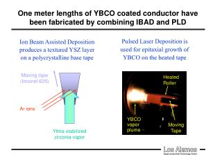
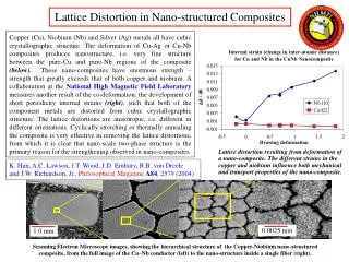
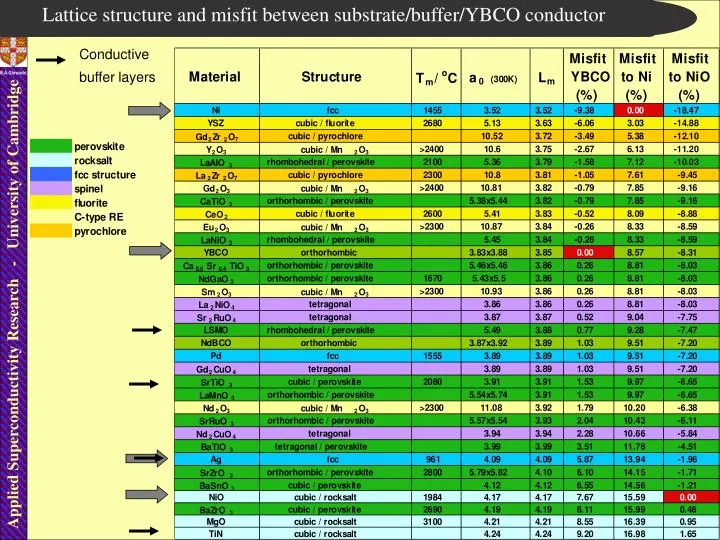
Lattice structure and misfit between substrate/buffer/YBCO conductor Conductive buffer layers
Twisted conductor • - large circulating currents can exist among the filaments due to connections at the ends (in current leads) • ac losses may increase by one order of magnitude or more in dependence on the distance between the filaments and the resistance at the end. • the filaments must be transposed (or twisted) at least one time in the middle of the length provided that the magnetic field is exactly symmetric along both half lengths • twisted decoupled filaments - ac loss reduction coefficient
3) multifilamentary tapes in a transverse magnetic field - hysteresis losses in perpendicular magnetic field - about 2-3 orders of magnitude higher than in parallel field Ho - amplitude of the applied magnetic field Ho w - tape width t - tape thickness • for decoupled filaments - ac loss reduction directly proportional to the number of filaments (proved experimentaly)
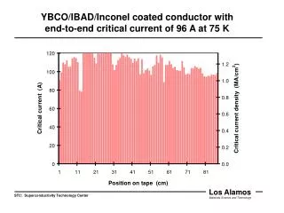
Multifilamentary YBa2Cu3O7 Coated Conductor IRC in Superconductivity testing 1cm CC-20 filaments CC-1filament Single filament < 500mm
AC field AC current anisotropy at the IRC in Superconductivity In phase and out of phase measurements for transformers and generators QI/Q||~100 (high precision of angle required in parallel field - of the order of 0.1 degree) Magnet requirement for YBCO coated conductors in supergenerators is about 2T/400 Hz Current AC magnet capability
Division to smaller filaments essential for Ha perp. to ab plane
Current percolation through the dislocations HREM of LAGB [N.D. Browning et al, Micron 30, 425 (1999)] Important factors: • conductor aspect ratio • magnetic field angle • sample history • shunt layers, contacts length I width
Influence of misoriented Ni grains on YBCO layer Applied Superconductivity Research NiO layer grown by surface oxidation epitaxy CSTO grown by PLD via an amorphous route YBCO grown by PLD CuO precipitates
Current percolation in In-plane and out of plane misoriented GB 2° 4° 6° 8° 0.25 w=3 w=5 0.2 w=9 w=17 w=33 0.15 w=129 c0 w=513 /J c J 0.1 0.05 0 1 10 100 1000 10000 Length (no. of grains) The EBS maps above show regions misoriented by 2°, 4°, 6°, and 8° in a small area of the NiFe substrate. Using a model with a 2D array of R rows and C columns of hexagonal grains (shown above left), a number of parameters may be assessed over a range of threshold angles. 1 filament 5 filaments 11 filaments Recommended division of the coated conductors to narrower tracks/filaments is a compromise between reduction of the current in the longer tracks and gain in reduction of AC losses.
2-D Grain growth modelling IBAD and RABIT MCS = 2 MCS = 25 MCS = 100 p=1 p=5 A New Grain Structure Model A Monte-Carlo grain growth model has been used to simulate more realistic grain structures. The grains are initially made up of single square pixels. Each pixel has an energy based upon the number of neighbours which are in the same grain. High energy pixels are consumed by neighboring grains. As the simulation progresses, grain structures such as those below develop. The average grain size in pixels (p) is related to MCS. The figures above shows grain structures for p=1 (simple square model) and p=5, both for samples 25 grains long and 10 grains wide. After N Monte-Carlo Steps (MCS) each pixel will, on average have been considered N times.
Ic vs length and width of Coated Conductor 1 cm 1/NW 10 km (1/NL) Ic Ic Nw=300 grains 102 104 104 Nw=100 grains 106 NL 102 NW 108 Nw=30 grains Nw=10 grains … a useful working approximation is [Rutter and Goyal MRS 2003]
Orientation of the GB in respect to the applied magnetic field is important In plane critical current vs magnetic field measurements on YBCO thin films: (a) angular dependence of the critical current crossing low angle grain boundary at 8T. For the higher GB angle the minimum is wider and the absolute valuses are substantially lower; =90o represents Lorentz force-free configuration. Hexagons represent grains whereas black outlines of hexagons represent grain boundaries; (b) schematic of the Jc vs (B,) in plain measurements. Elongated hexagonal grains have the better percoative properties than the simple hexagonal ones. There is a difference in the response of hexagonal grains if all of them are aligned.
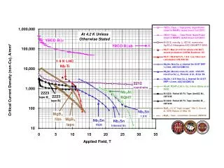
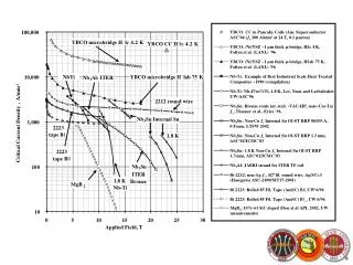
Solution for the high magnetic field and low temperature magnet applications NbTi + Nb3Sn + NbTi3(Sn,Ta) = 22.59T additional magnetic field generated by Bi-2212 coil = 1.46T ; total field > 24T (a) (b) High magnetic field superconducting electromagnet. (a) schematic cross section of the multi-section hybrid electromagnet. The materials used are NbTi + Nb3Sn + NbTi3(Sn,Ta) resulting in 22.59 Tesla and if additional magnetic field is generated by internal coil in the centre it would generate an additional field. The total magnetic field in such a hybrid configuration, currently exceeds 24 Tesla. (b) schematic outline of the favourable grain structure of the internal HTS coil made from the YBa2Cu2O7 coated conductor.
3) multifilamentary tapes in a transverse magnetic field Presence of the magnetic material can have a detrimental and also beneficial influence on the reduction of AC losses and increase of Jc of superconductors. This problem is particularly important in case of the coated conductors and multifilamentary wires. The latest research on the multifilamentary conductors surrounded by magnetic material proved that losses can be reduced substantially according to eq.1 by coating individual filaments by magnetic material. By comparing losses in a standard multifilamentary superconductor, Qst, to losses in a multifilamentary superconductor with the magnetic covers around individual filaments, Qcov, at the same reduced current i, one can obtain magnetic decoupling loss reduction coefficient, Kmd, (eq.1); where i=I/Ic Ic1=Ic/N, N number of filaments. The parameters k(i) and are to be determined from experiment and represent individual filament. (eq.1)
Minimisation of AC losses Magnetic decoupling Recommended division of the coated conductors to narrower tracks/filaments is a compromise between reduction of the current in the longer tracks and gain in reduction of AC losses.